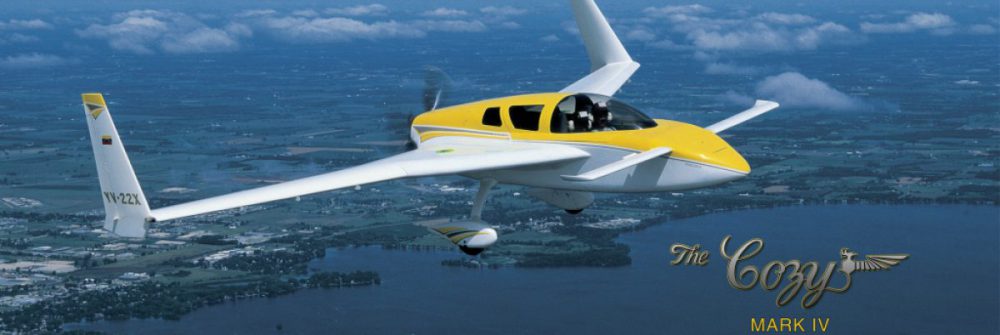
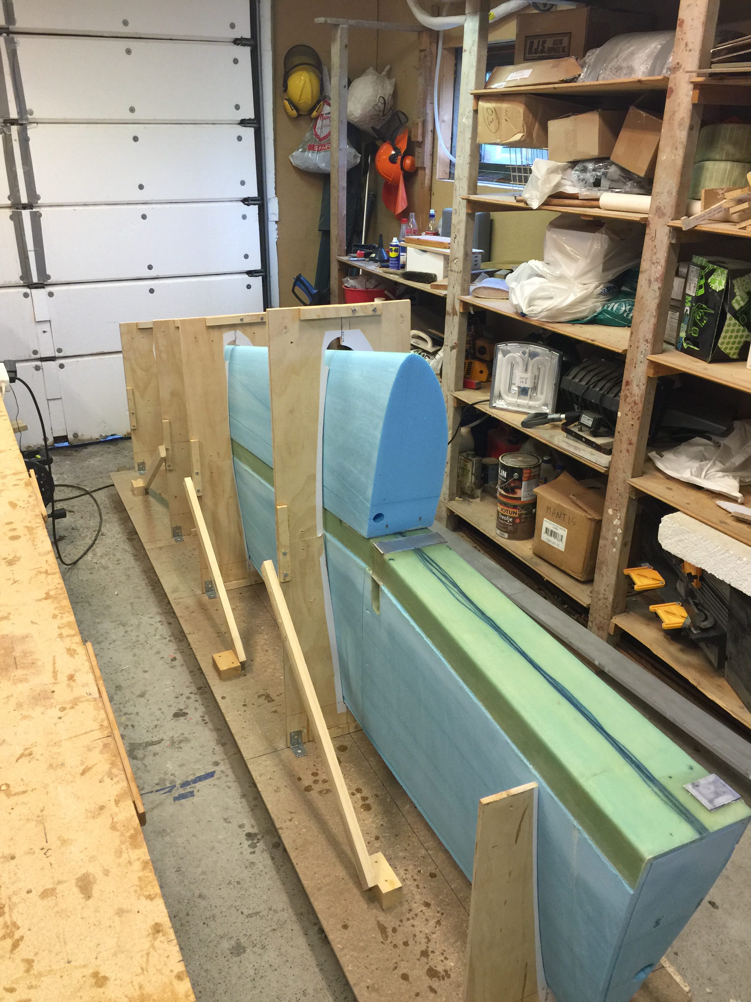
2016-04-04: Moved the fuselage outside and wrapped it in some tarpaulin. I needed the space to be able to move freely around the wing.
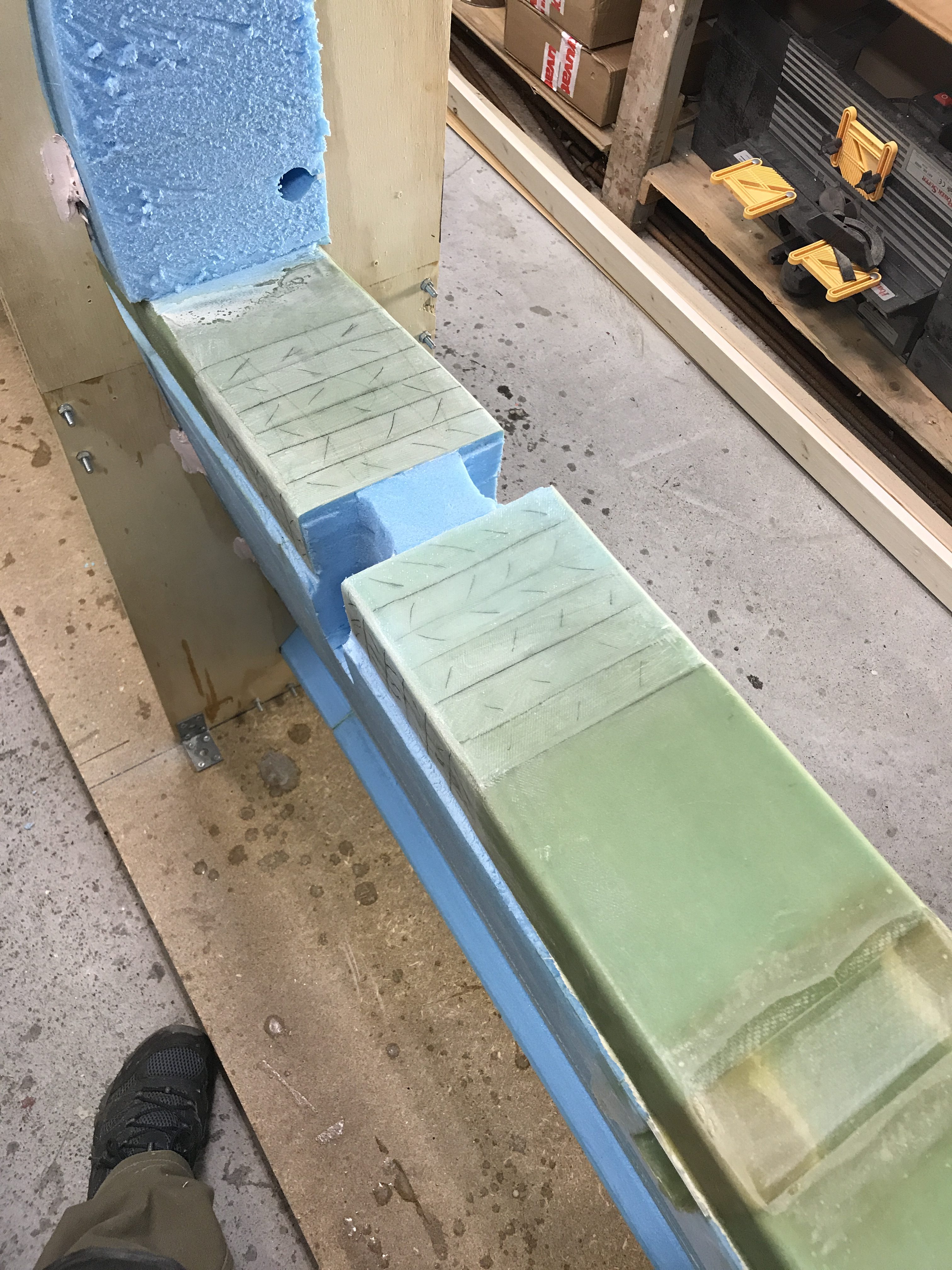
Mounted the cores in the jig and microed them together. As several other have discovered the mating surfaces between the cores (FC1, FC2 and FC3) was not absolutely straight despite all efforts to cut in level and 90 degrees. I used a straight edge to be sure that the upper surface was straight, since this is the mating surface to the leading edge cores (FC4 and FC5). The gap is visible in the nect picture. I will simply fill this with dry micro later.
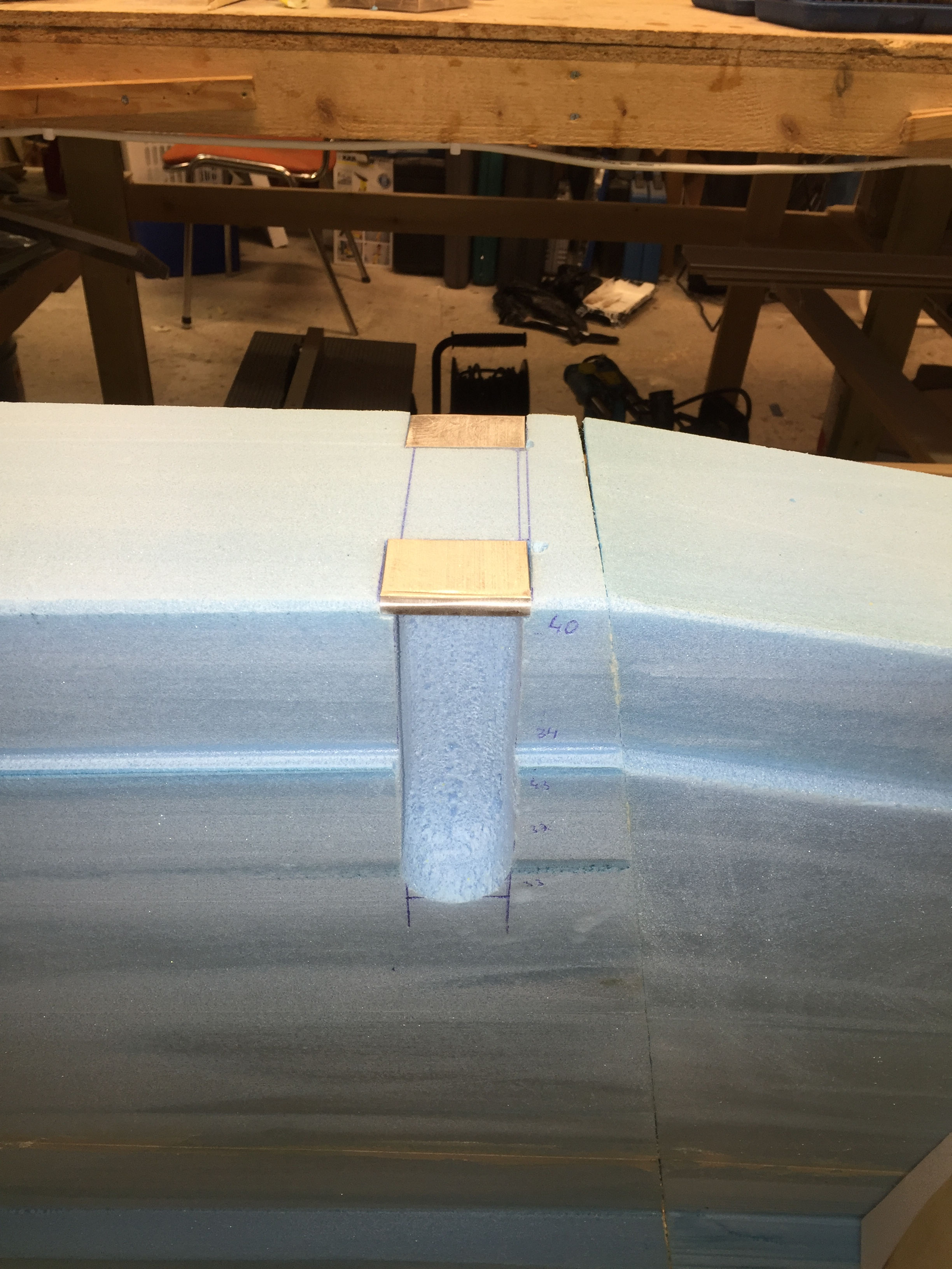
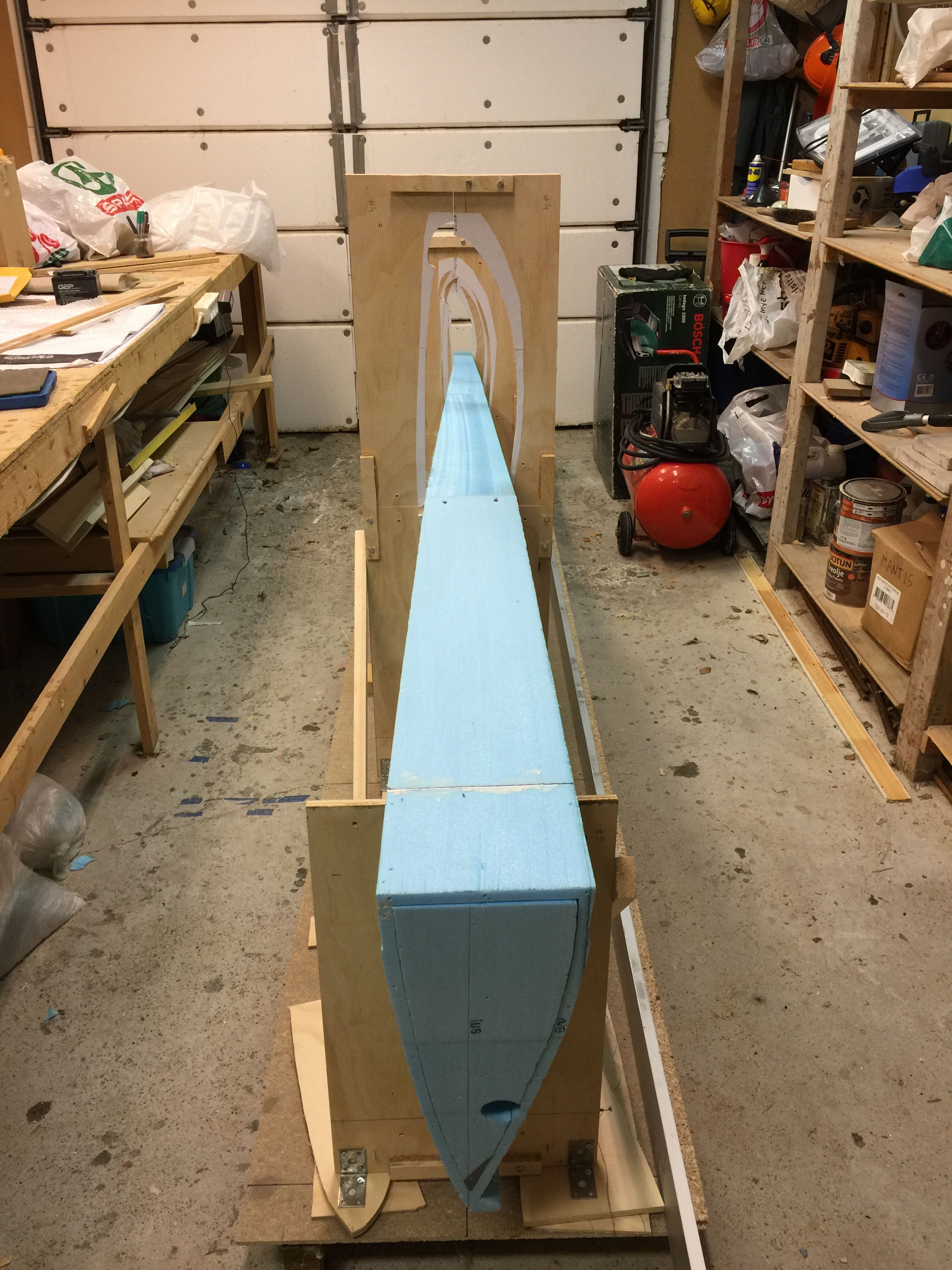
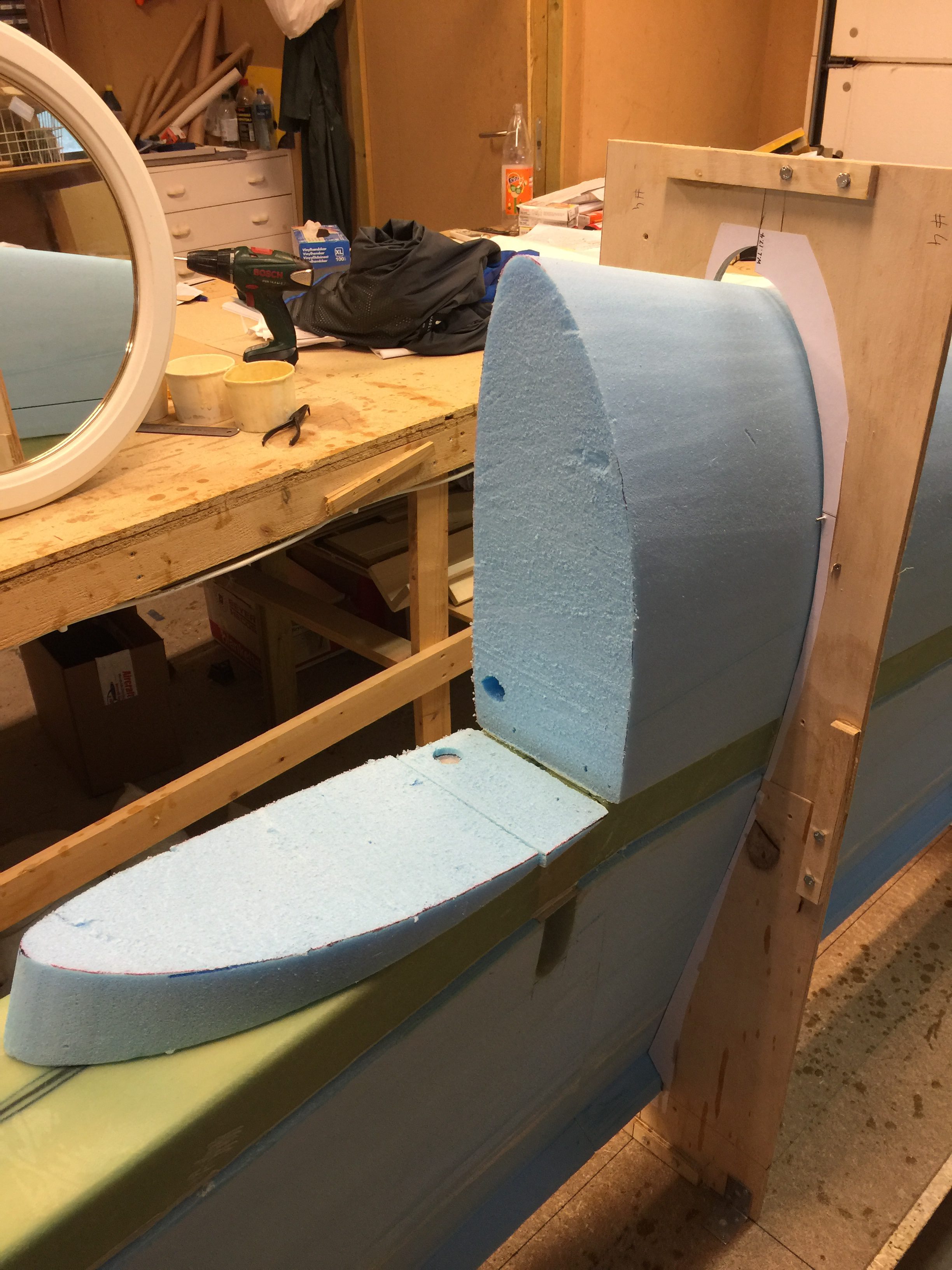
2016-04-18: I routed the wing attach depressions on FC1 using my Dremel and a sharp knife. Using the Dremel with a sanding drum is a quick way to remove foam, but go easy on the speed. Using max speed will result in melting the foam. Run at 1/2 speed and it will be ok. I also cut the notches in the shear web for the hardpoints LWA4 and LWA6.
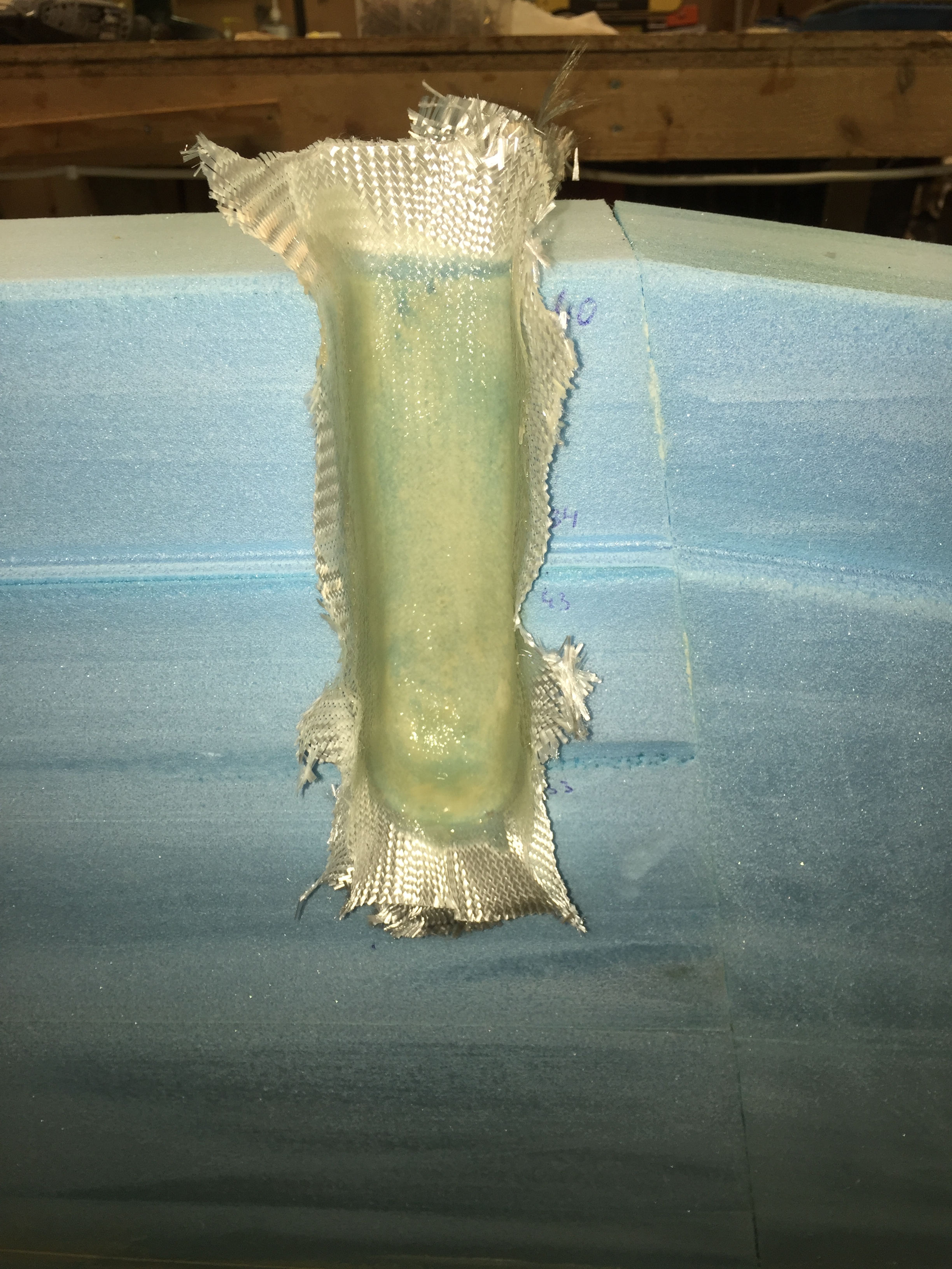
2016-04-18: Glassed the inside of the depressions with 2 BID.

2016-05-16: I had to wait 4 weeks to continue, since the metal sheet for fabricating W18 (0.016″ alu) was out of stock at ACS. I made an order for all the screws and stuff for ch19 that I was missing, but this little item was in backorder for several weeks. Finally got the shipment and was able to fabricate the little metal cover. However – I do wonder why we couldn’t make this of a couple of plies with BID? Just make a plug and fabricate the cover out of glass would be a very easy task. Well – now it’s done and time to think forward.
2016-06-26: Still another pause. This time domestic duties had to be proritized before the plane. Repainting the house takes time :-).
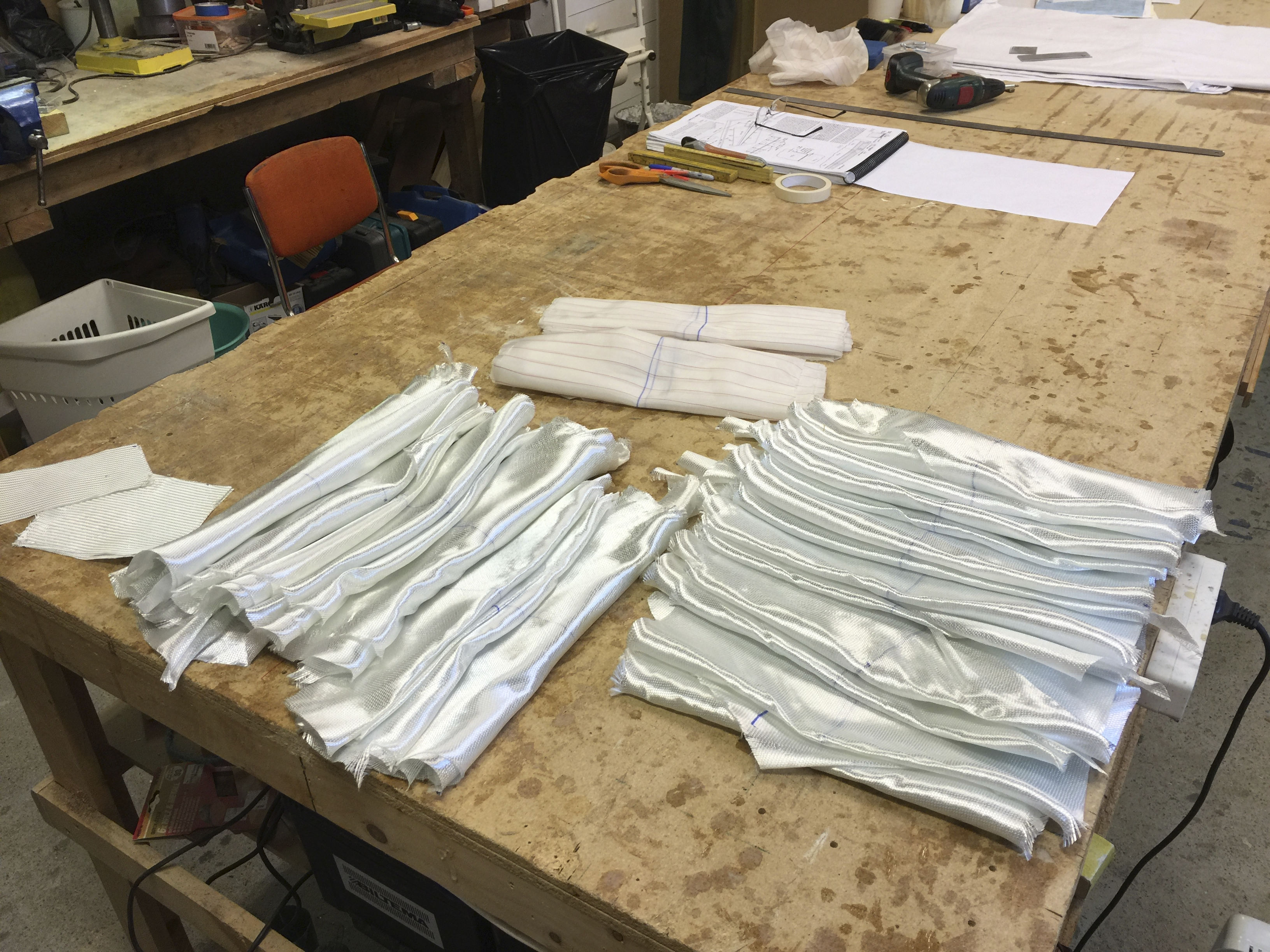
Finally got to work a full day in the shop. Started with cutting all the glass for the shear web.
2016-06-26: Then I masked off the foam below the shear web to avoid epoxy dripping on the foam.

2018-08-11: Masking the left wing a bit different – using plastic instead of brown paper.
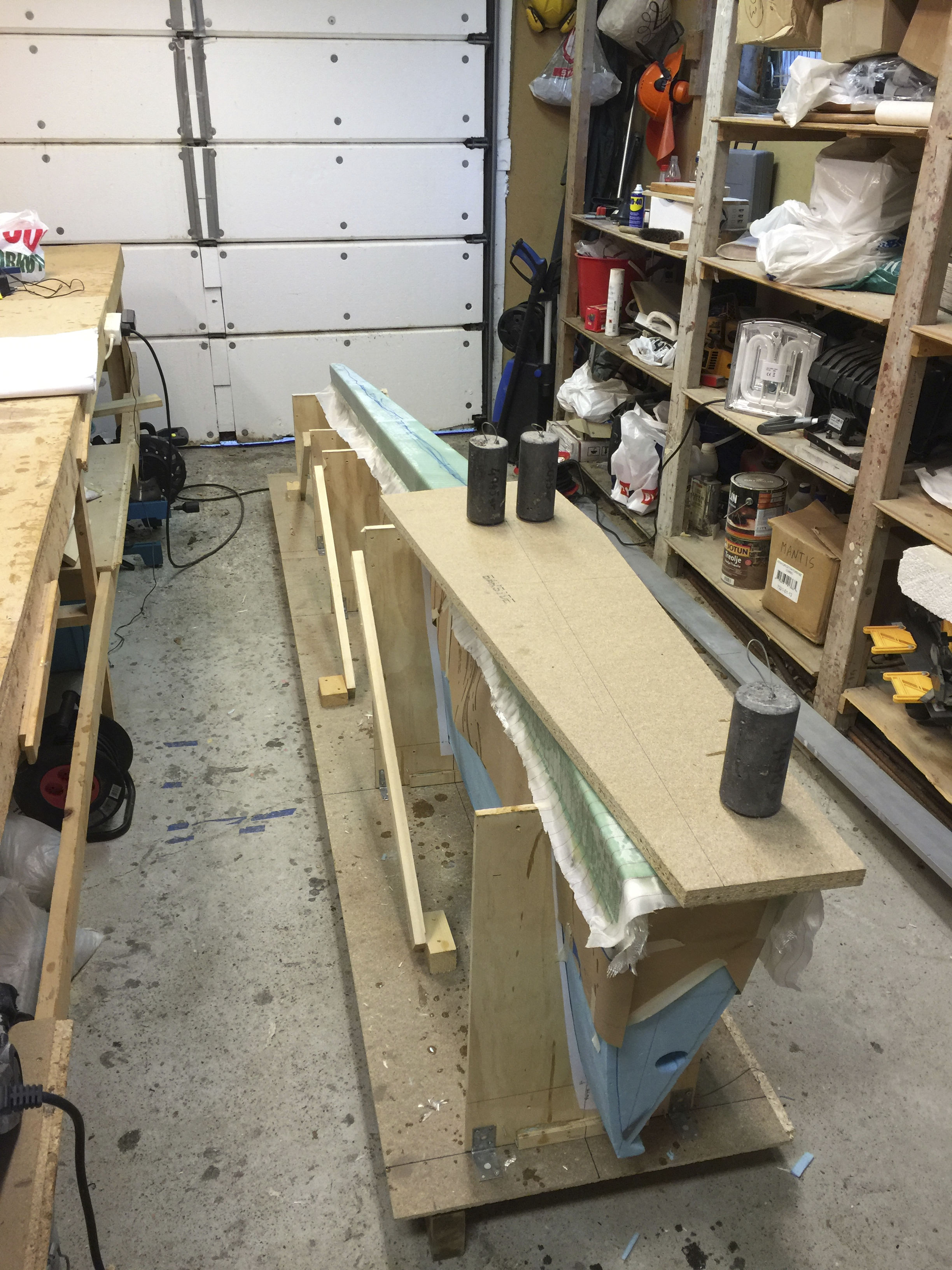
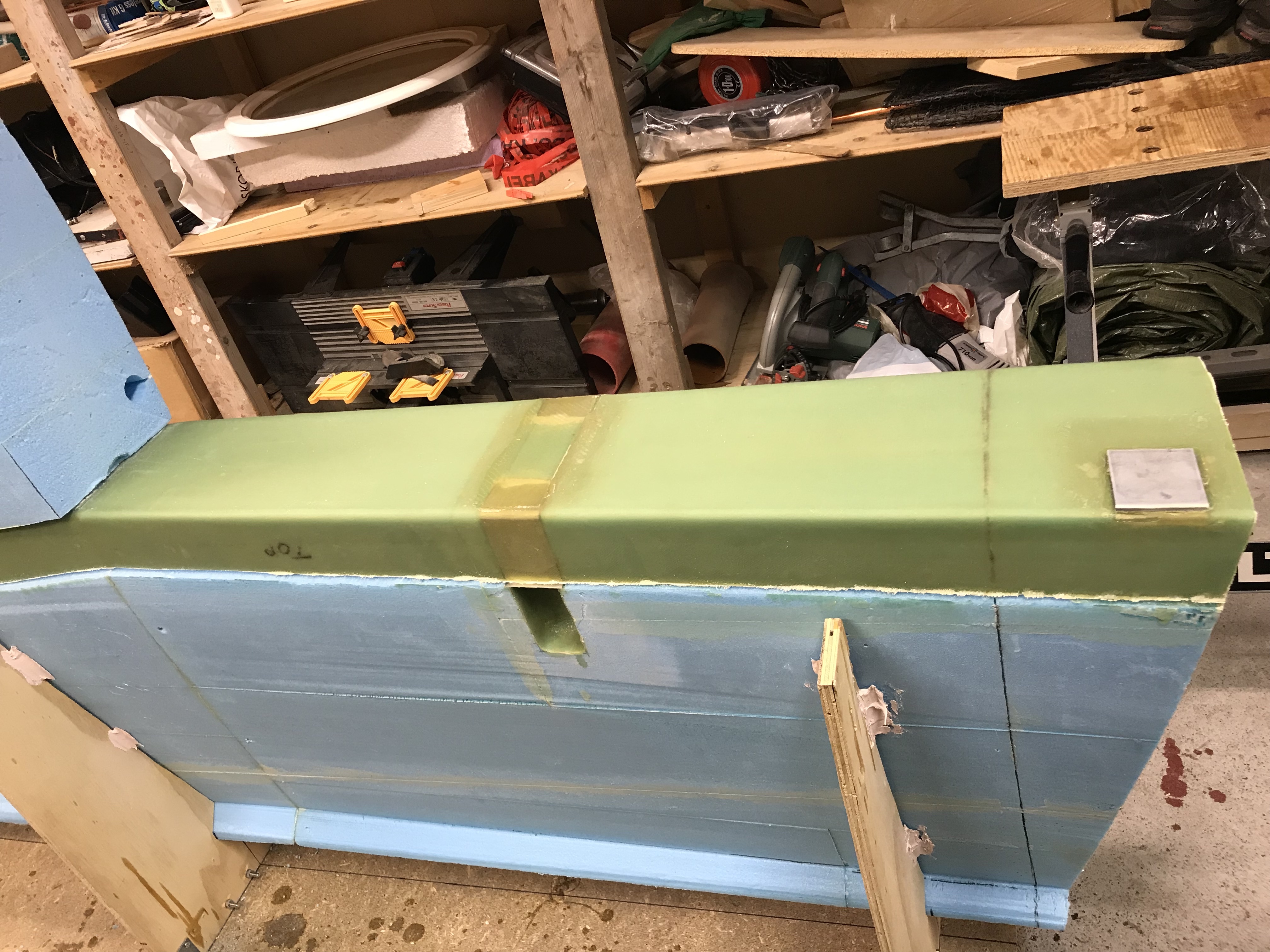
2016-06-26: Finally I glassed the shear web and epoxied the two aluminum parts LWA2 and LWA3 in place, and weighed down according to plans.
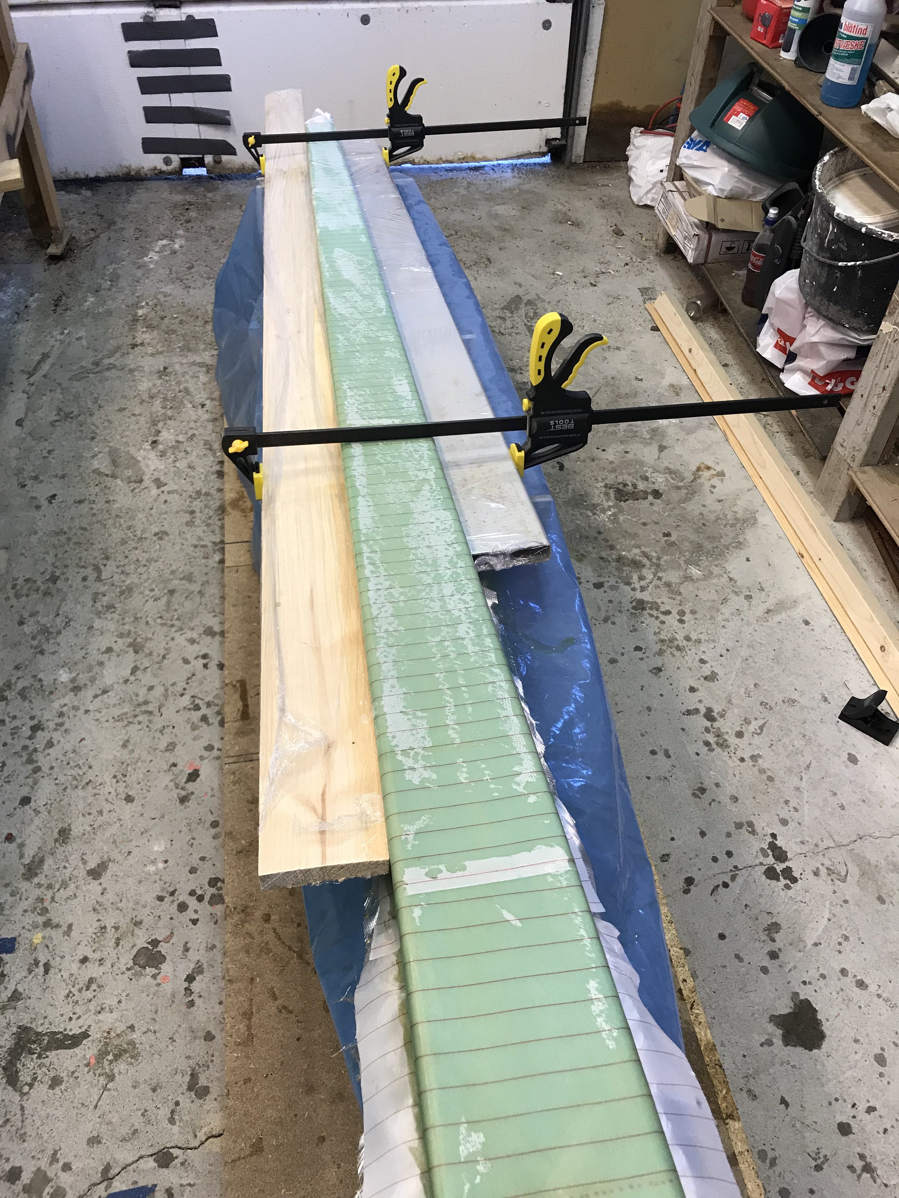
2018-08-12: Glassed the shear web on left wing. I discovered that the outboard foam core was a bit curved, so I used to straight boards to force the cores back to the proper shape while the glass is curing.
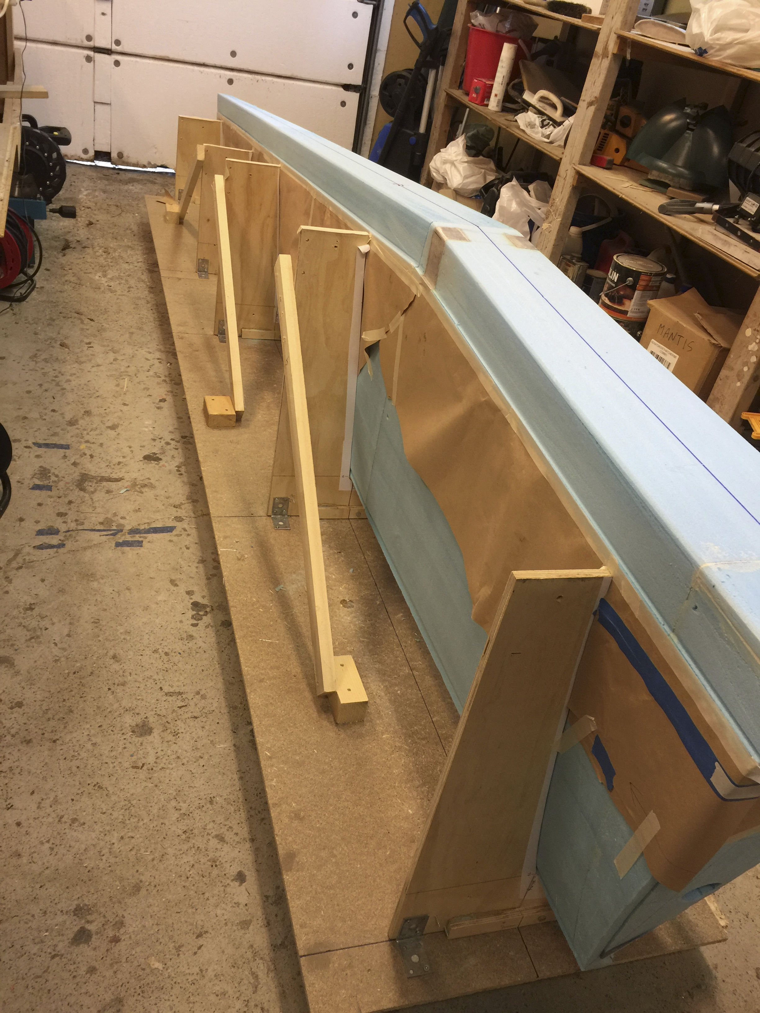
2016-06-27: Removed the masking tape and paper, used the multi tool to touch up the edges f the shear web in the spar cap depressions. Glued the top cores to the shear web and mounted the front part of the jigs again. Set to cure.
2016-07-10: Cut off the corner of FC4 as per plans.
My first big goof up!
2018-09-17: Admiring my superb work on the shear web on the second wing, mentally preparing for step 5, I sensed there was something odd with the inboard part of the wing.
Ouch…. the wing attachment depressions and hardpoints are completly misplaced! Reading the manual once more:
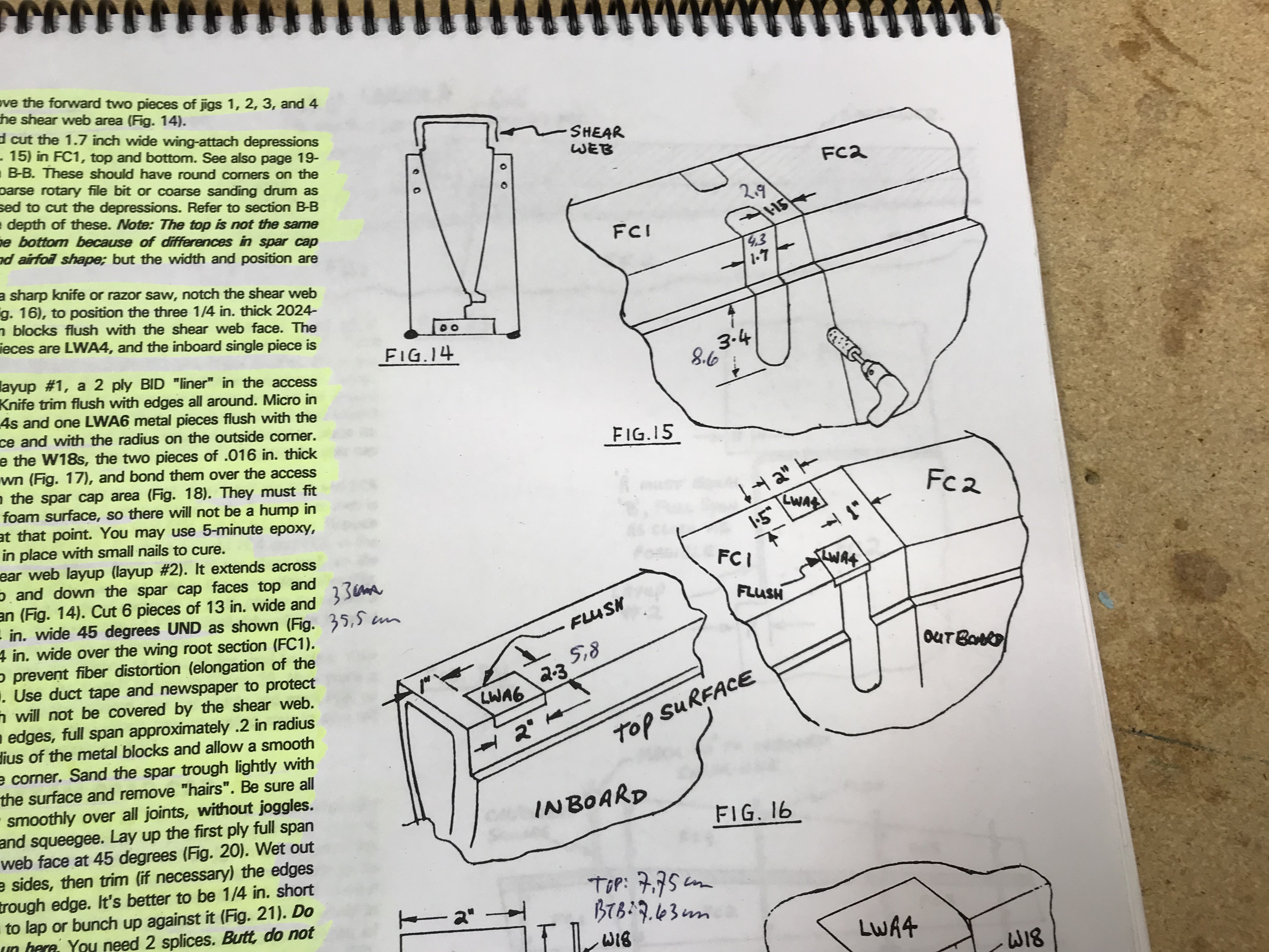
clearly points out the mistake. After banging my head in the table for an hour or so, I first managed to establish how I managed to screw this up. In the drawing LW4 is placed 1″ inboard of the transistion between FC1 and FC2. Examining my version, I saw that 1″ outboard of LW4 I have a seam in the foam block. This was due to me gluing together several foam blocks to make a FC1-block. I did actually just identify “a seam” in the foam and started to work without actually checking with the manual. Remember: Measure twice, cut once.
I need to repair this, obviously. Scrapping the whole wing is not neccessary. I consulted with the community and got an affirmation from Marc Z that it was ok to use the standard repair method described in the manual. This means that I have to make 6 overlapping plies of UNI, after carefully sanding down the layers one ply by one, with 1″ distance between the layers.
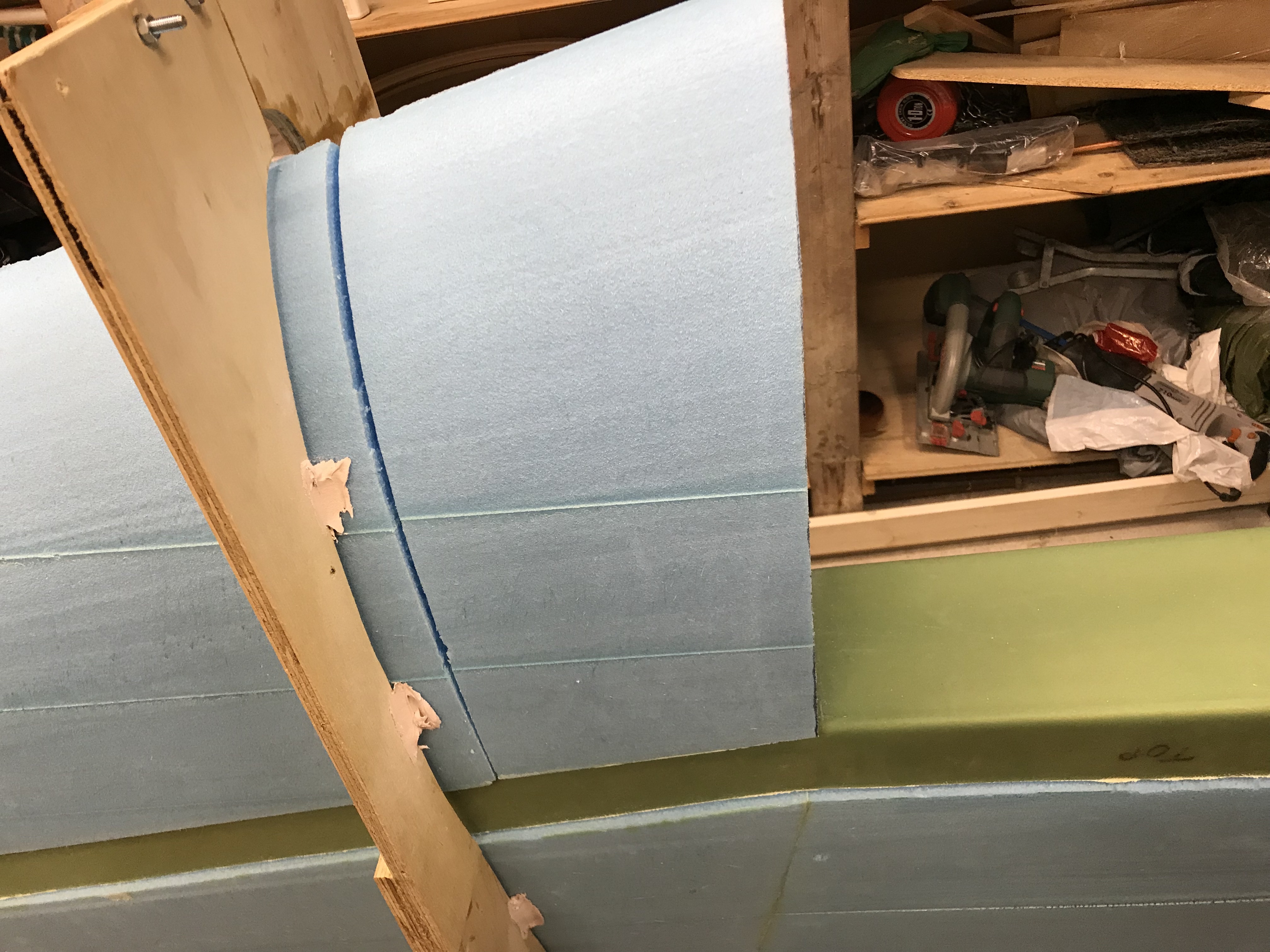
Had to cut away some of the wing foam to get enough shear web exposed.

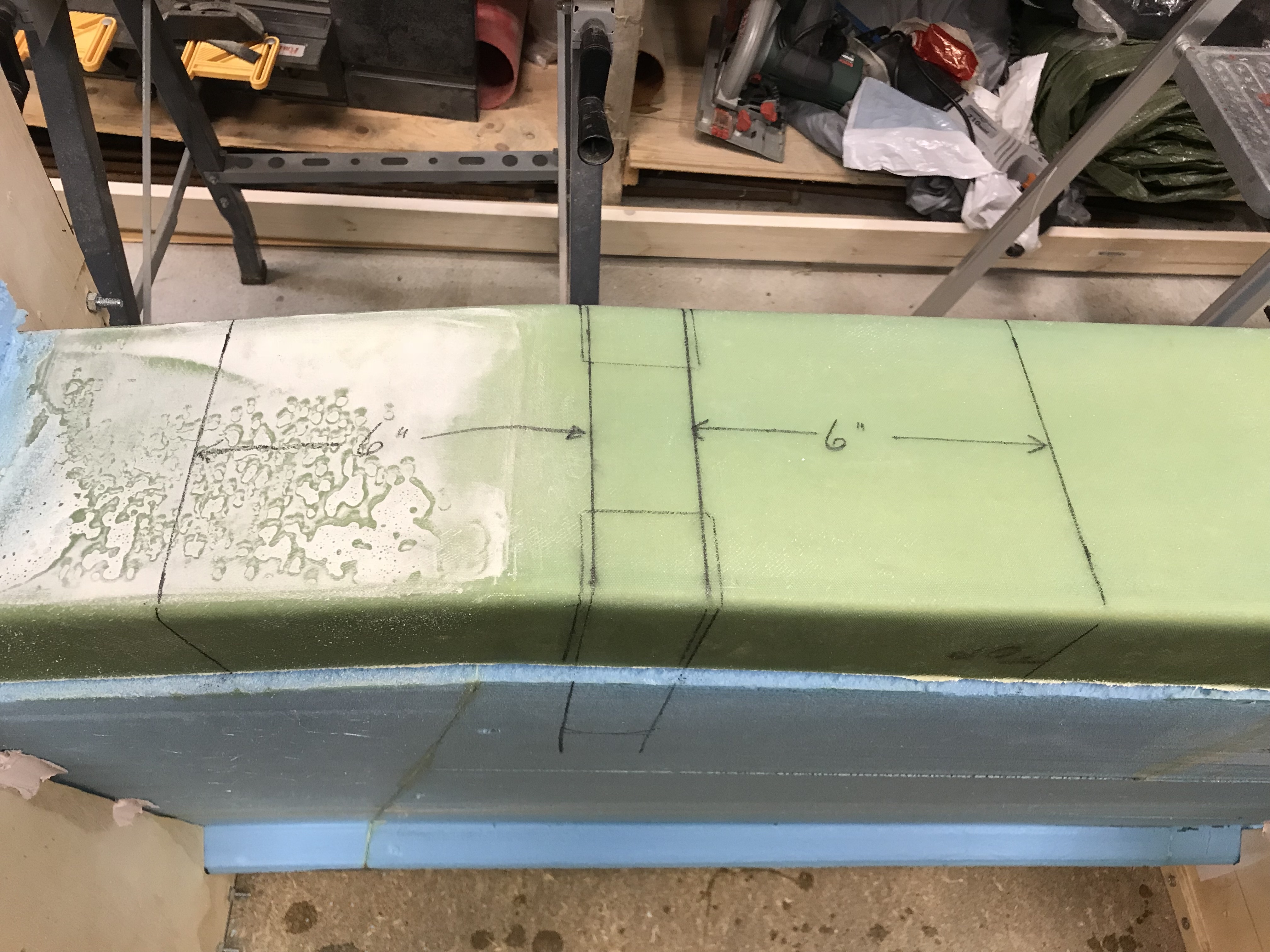
Then start to mark the correct position of the depressions as well as the area I need to do a repair job on.
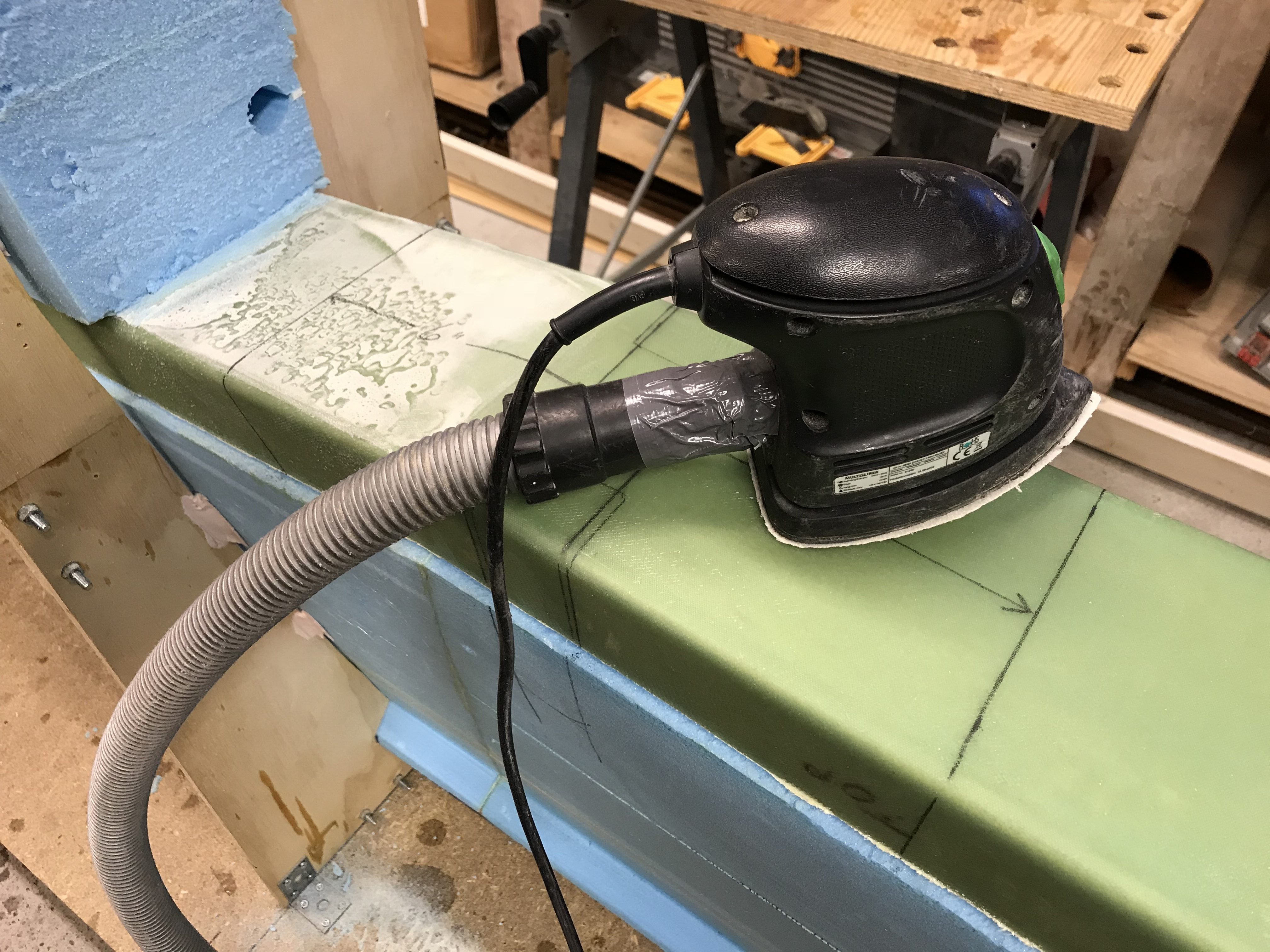
Using my little sander connected to my vacuum cleaner. This creates large amounts of glass dust that is unhealthy to inhale.
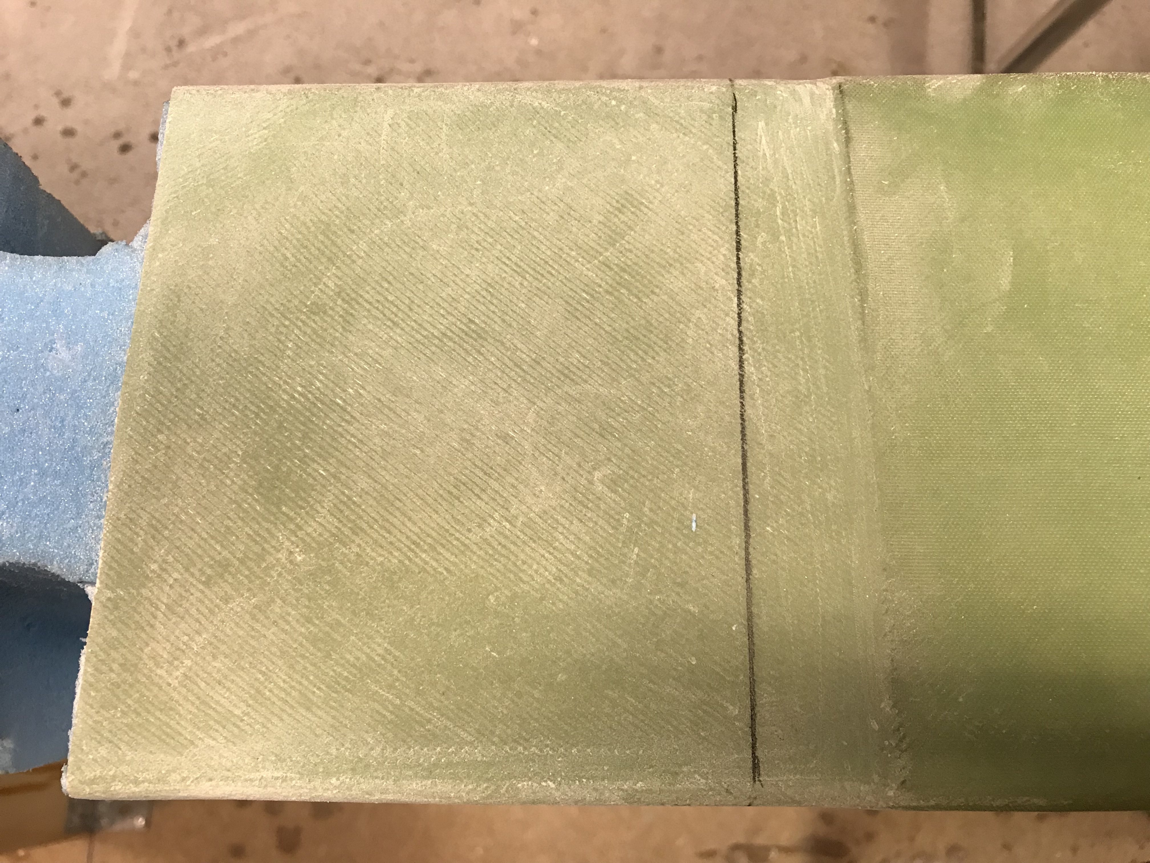
Very boring job, taking a lot of time. Need to be careful to sand one ply at a time. Since the plies have opposite directions I use this as an indicator to see when I have sanded through each ply.
2018-10-31:
At last I have come through all layers one by one. I have also prepared the wing attachment depressions and are ready to glass them first. I will leave the old LW4’s inside the shear web and just fill the depression holes with pour foam. No point in removing the hardpoints there.
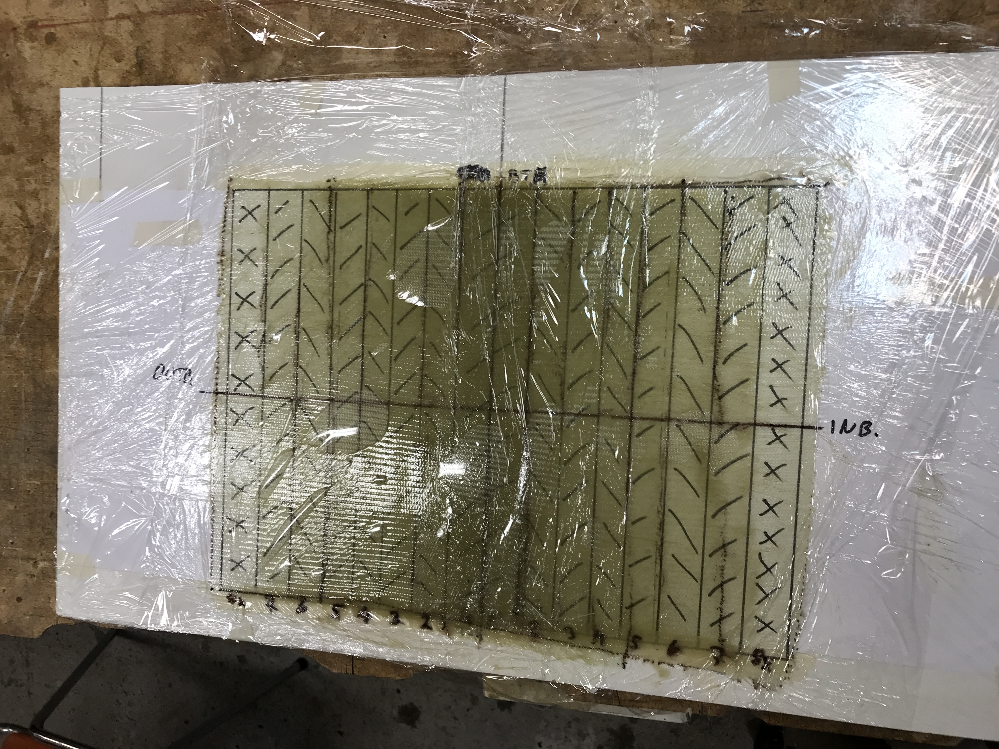
I chose to make the complete layup on plastic on the table to ensure that all the glass was controllable. UNI is not easy to handle in small plies. I draw the fiber orientation on the paper in the bottom for each ply. Finally I covered it with saran wrap. The layup as seen here is as it should be laied out on the wing. The airbubbles is just because of the saran wrap on top – I just carried the layup over to the wing and then removed the saran wrap again.
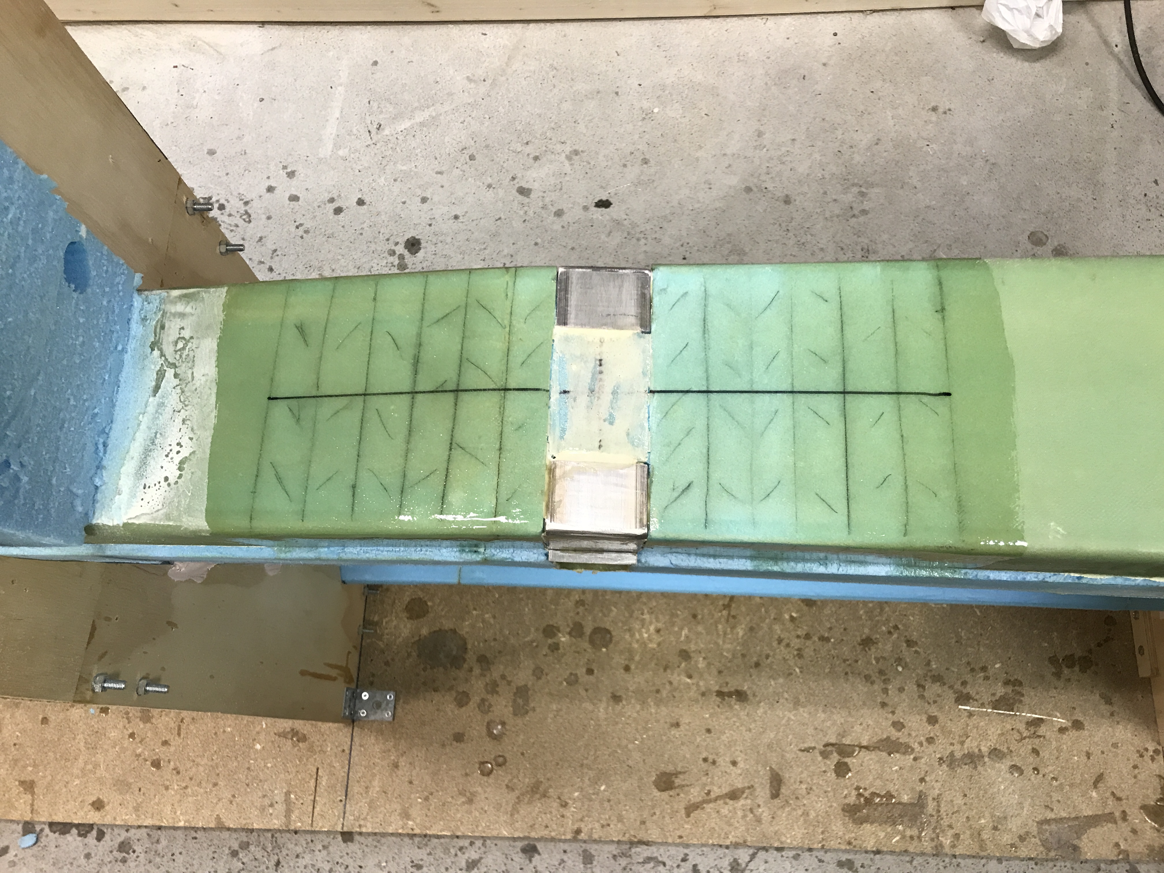
The wing area is prepped – micro on the part between the depressions (bare foam) and epoxy on the rest.
Here is the result after curing.
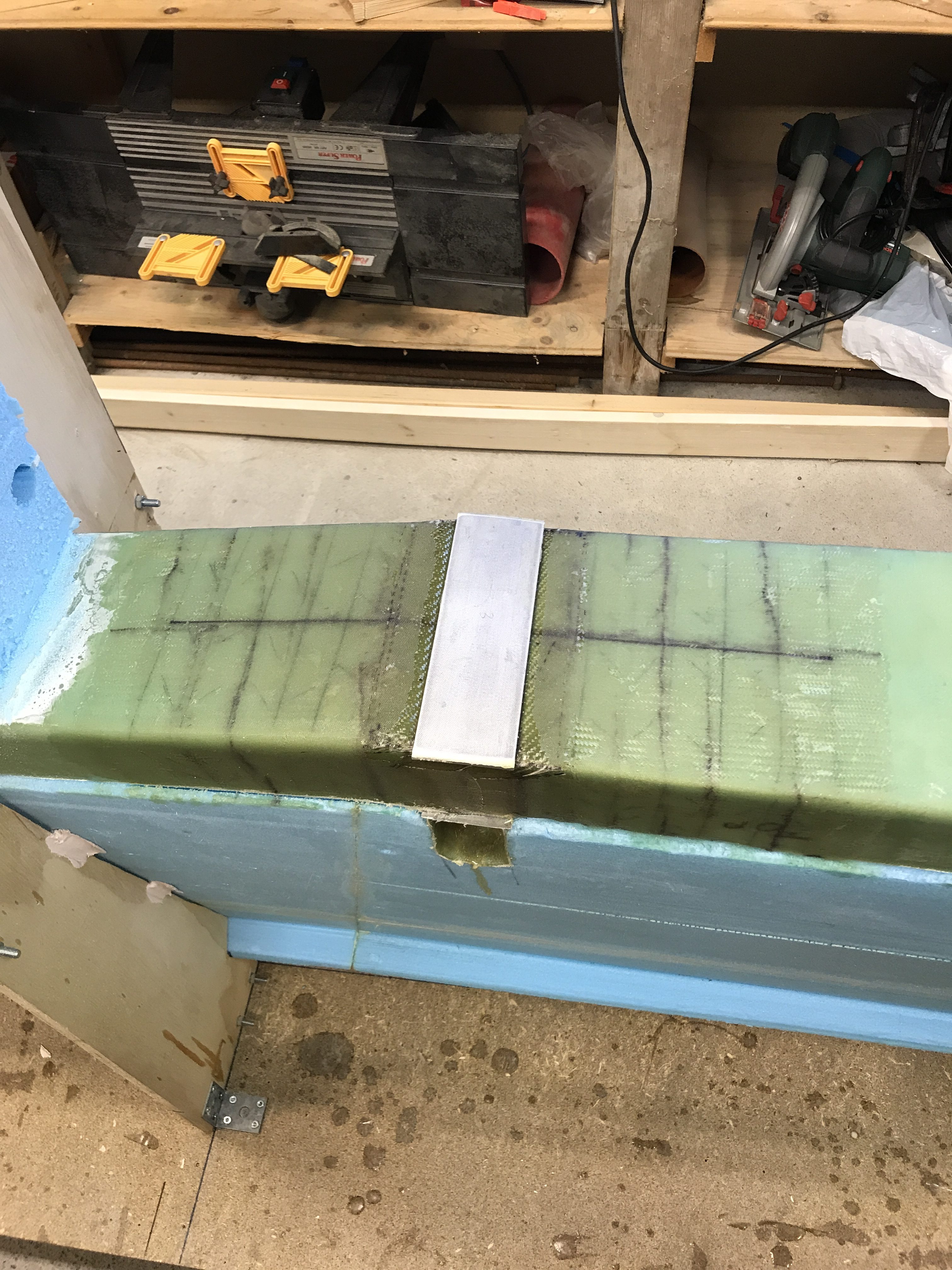
And after gluing back the foam part I cut away:
