
Starting with the NACA-scoop which is the intake for cooling-air for the engine. There are many ways to cool an engine, this way is the plans way, so it’s well proven. Since I plan to use a water-cooled-engine (as pr. March 2010 i.e.!) the cooling is a bit easier than for the regular air-cooled aircraft-engines. I will follow the plans and as usual call out if I divert from the plans. So – here we go!
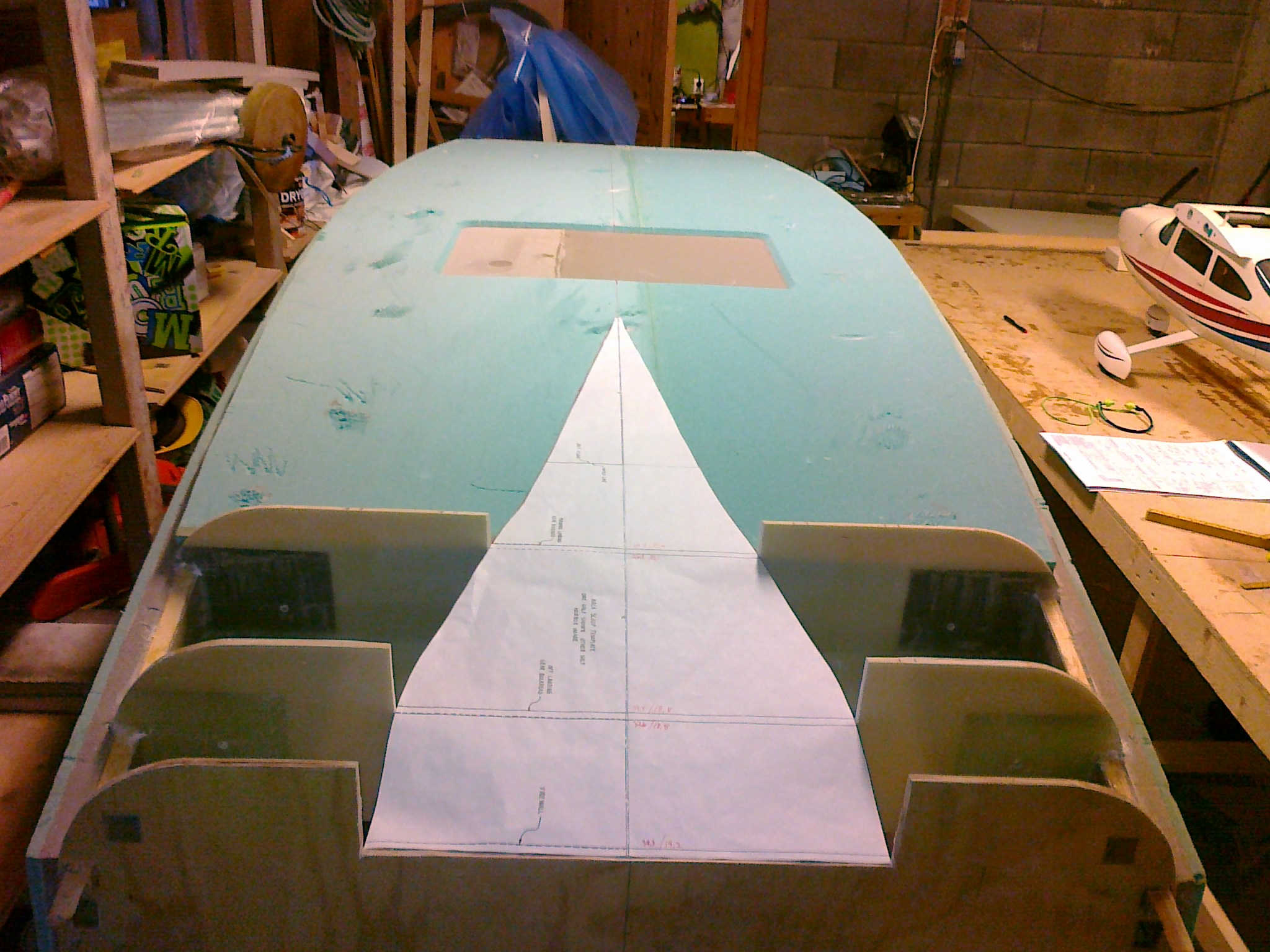
First I cut out the drawing of the NACA-scoop from the large-size-drawings. I then marked the outline on the foam and trimmed off some millimeters from the bulkheads to make it fit inside. Normally I don’t like to cut in the drawings but since I have the original drawings there was no problem this time. As one can see the bottom foam has some dents and scratches from the supportive frame that was bondoed ontop of it in chapter 6. I will fix this with dry micro when I am ready to glass the bottom.
On my work-table is my 1/4-scale Cessna 182. The snow is melting and soon I can start to fly my model-airplanes. Had to do some service on the model to make it ready for the season! Read more about the Cessna here (sorry – only in Norwegian). I used to believe that the Cessna was big. Not so anymore when I compare it with my Cozy 🙂
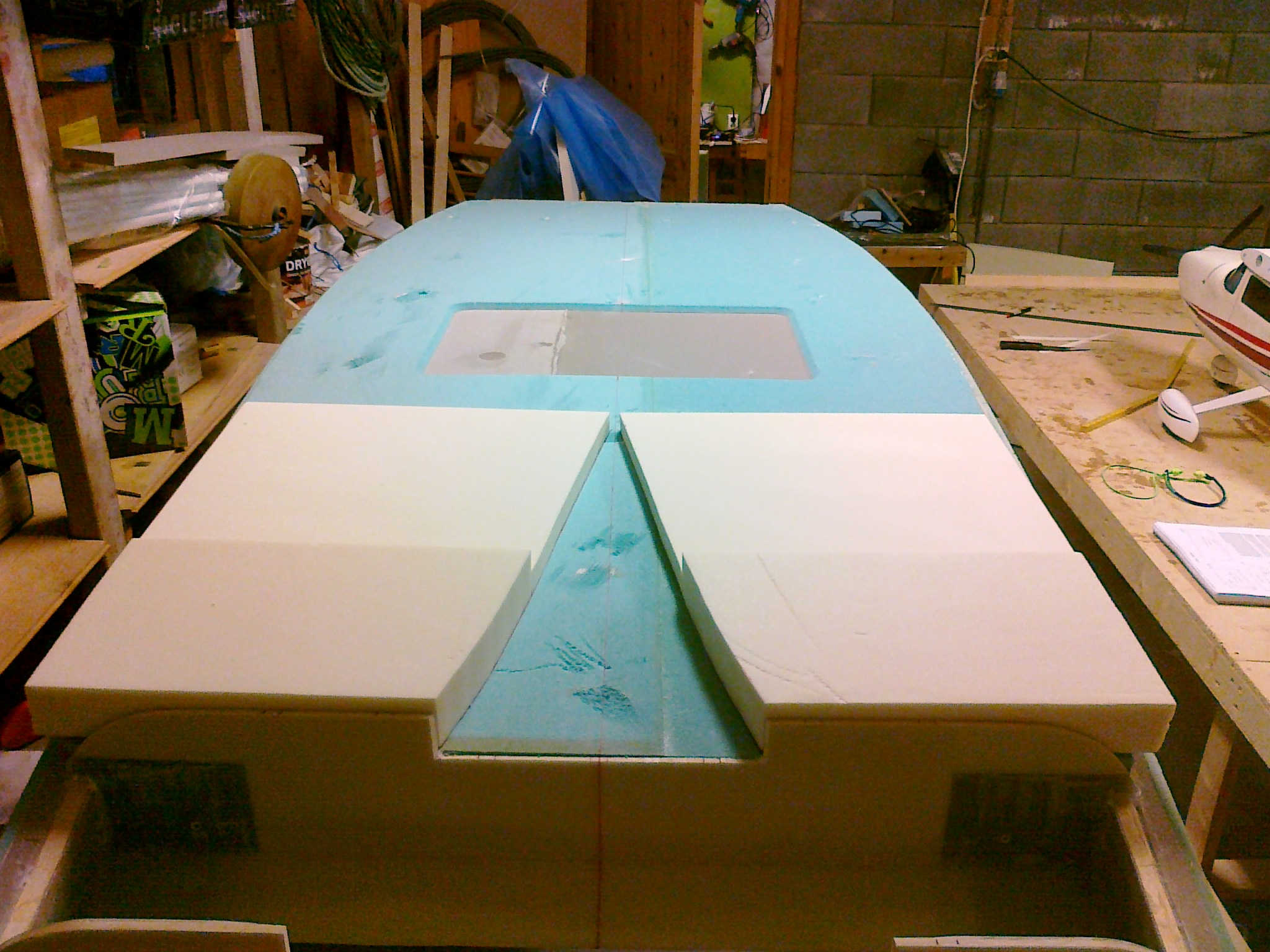
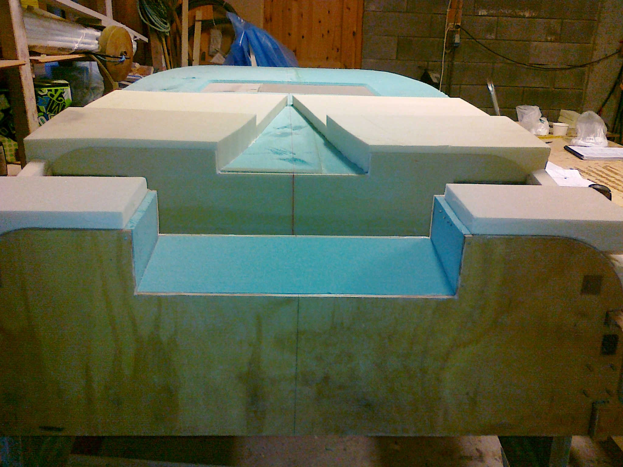
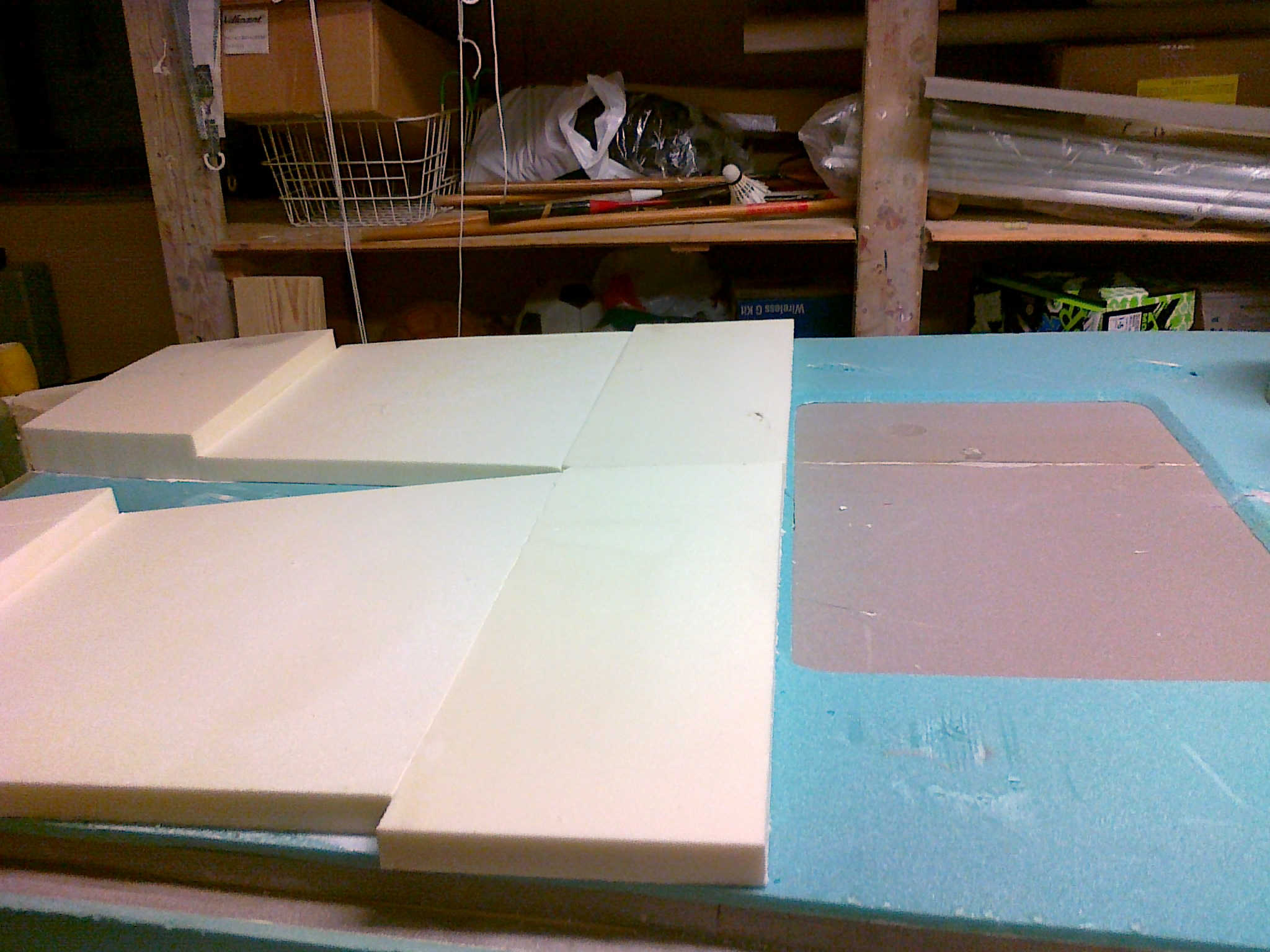
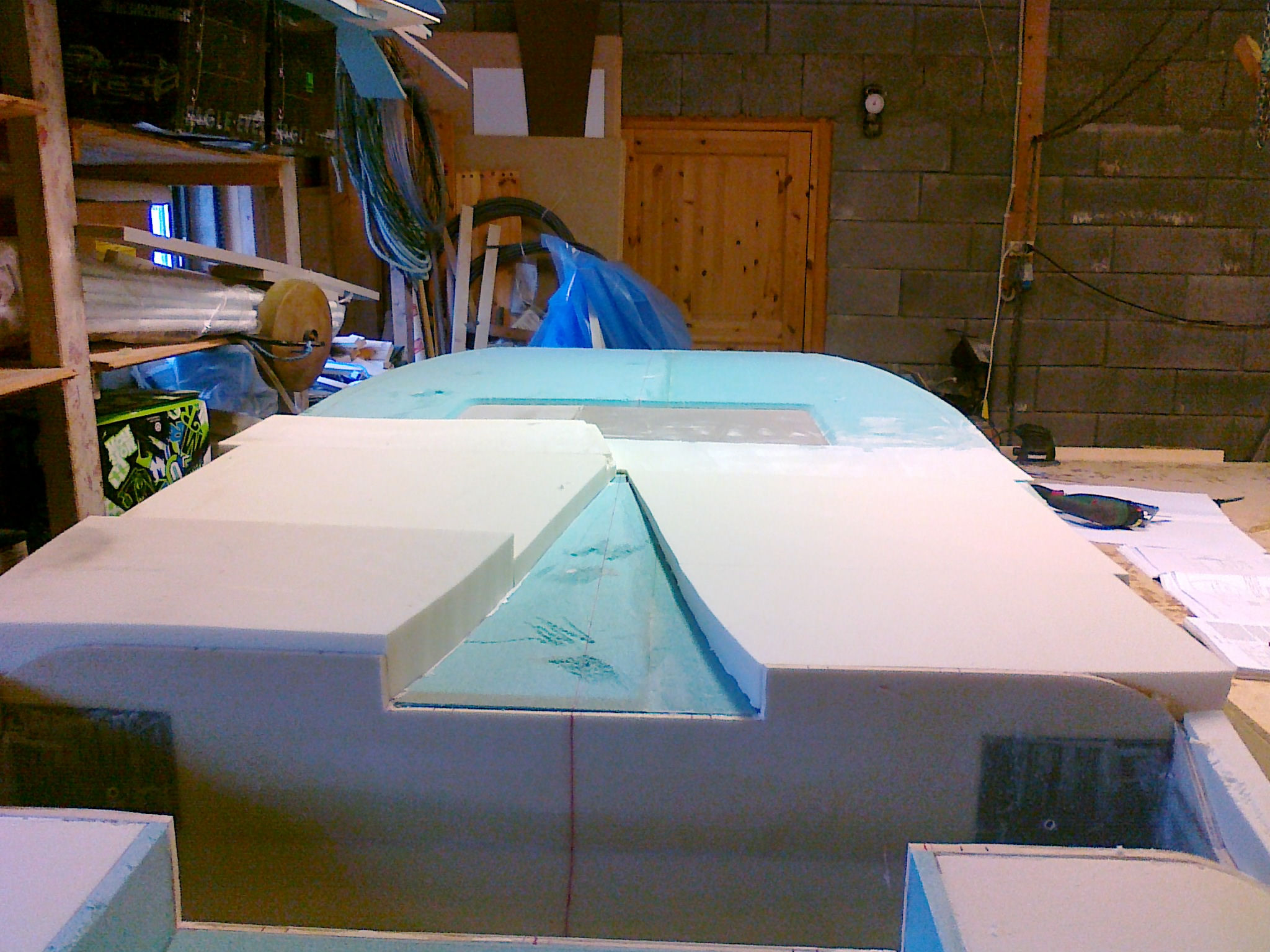
Next step was to cut four blocks of urethane (2″ and 1″ thick) and place them like the picture shows. Then I draw the shape of the NACA-scoop and cut it out on my jigsaw. The blocks are then microed to the fuselage-foam, the landing-gear-bulkhead and to each other. Then it is weighed down and let to cure.

Between the LG-bulkheads and the firewall I flox in place some plywood-braces. These are flush with the inside of the longerons.

On the outside of the plywood-braces I micro some urethane-blocks. Later I will shape these according to the shape given by the bulkheads.
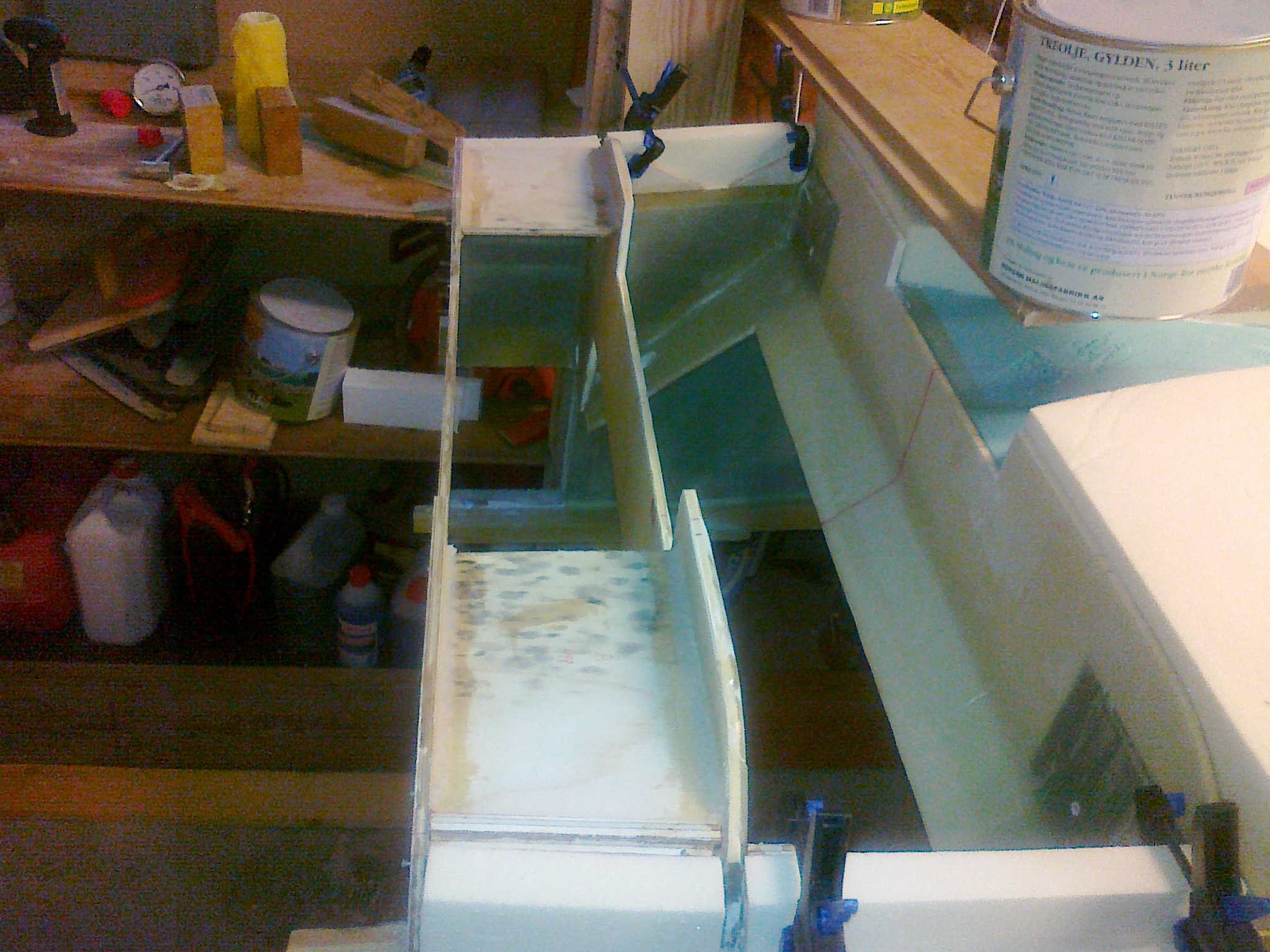
Plywood-braces is also floxed horizontally on both sides of the scoop between the aft LG and the firewall. Now it’s all set to cure.
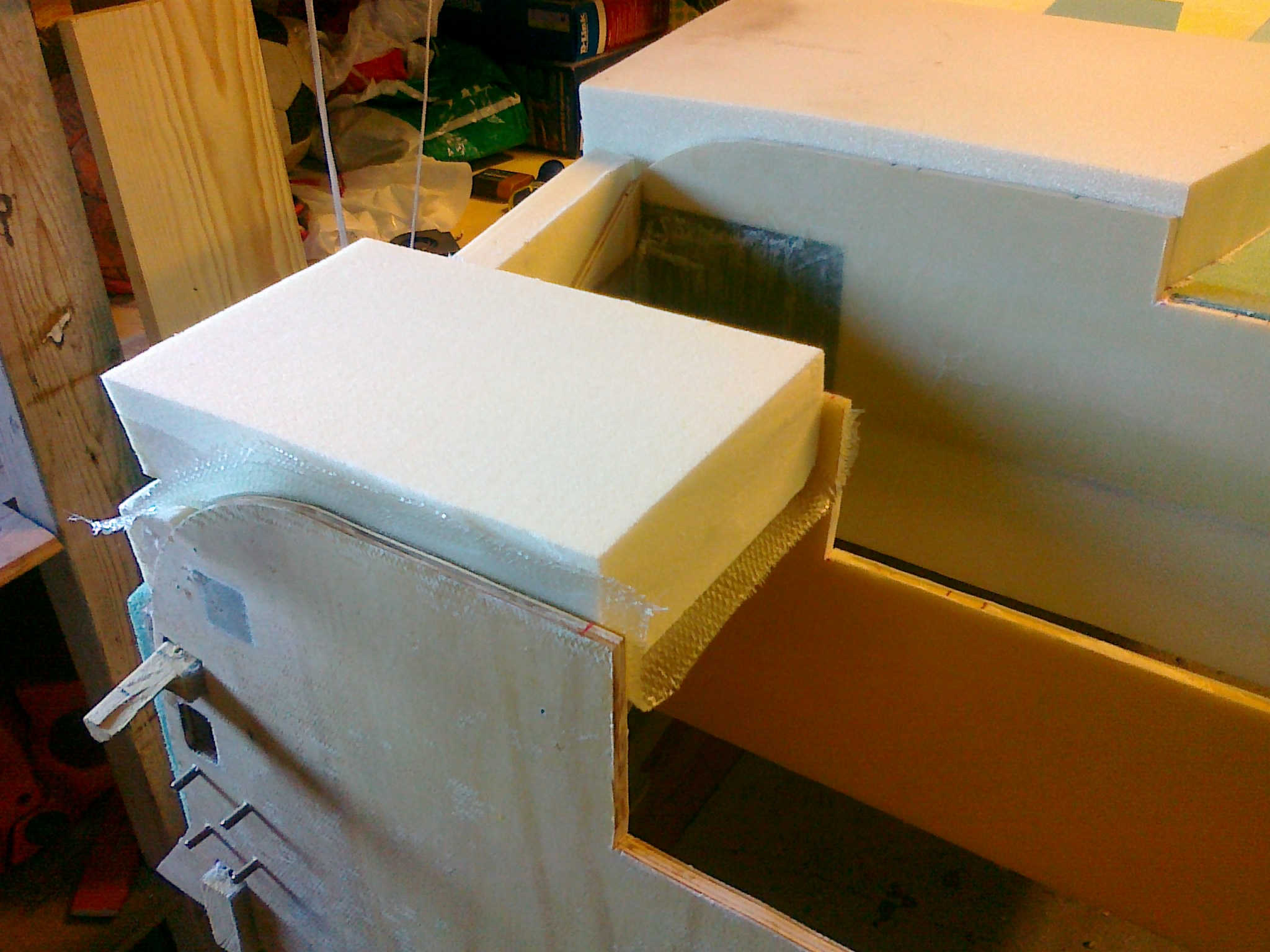
After cure I placed two plies of BID on the brace overlapping the aft LG and the FW. While still wet I microed blocks of urethane ontop of this. I will later knife-trim the glass so it follows the contour of the bulkheads.
Three pieces of 3/8″ H45 is then floxed between the aft LG and the firewall.
According to the plans I should make a 3/4″ flange (joggle as they call it in the plans) in the foam on both sides of the cavity for the landing-gear. In chapter 9 I will make a cover over this hole, and the cover will then be made to fit in the flange to make a nice surface without bumps. I will instead follow Wayne Hicks method and drop this flange.
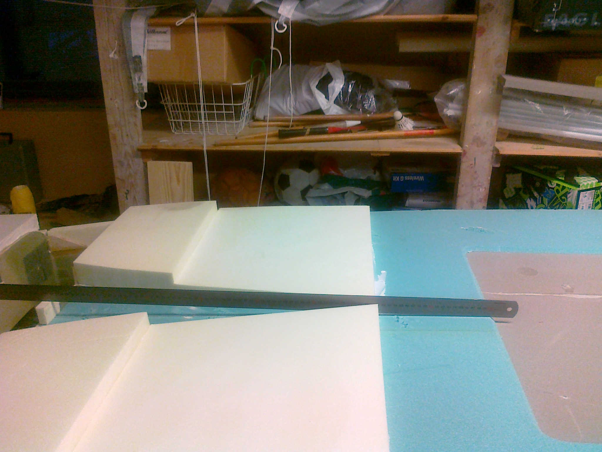
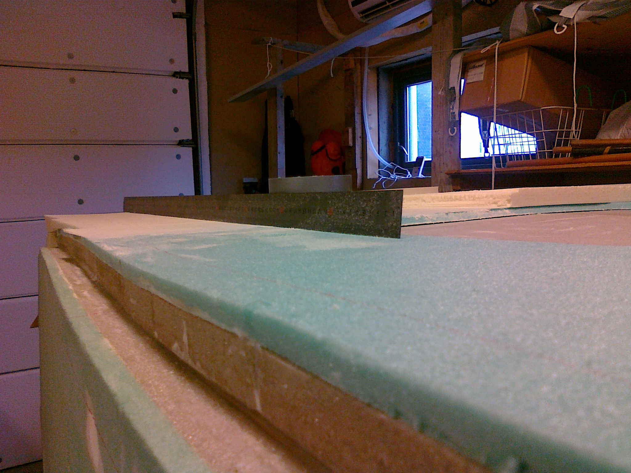
After reading some builders blogs and looking at my own construction it is clear that sanding the urethane according to the plans will create an angle approx. 8″ aft of the landing brake instead of a straight line. The ruler at the picture shows a gap if I place the end of the ruler at the aft position of the landing brake.
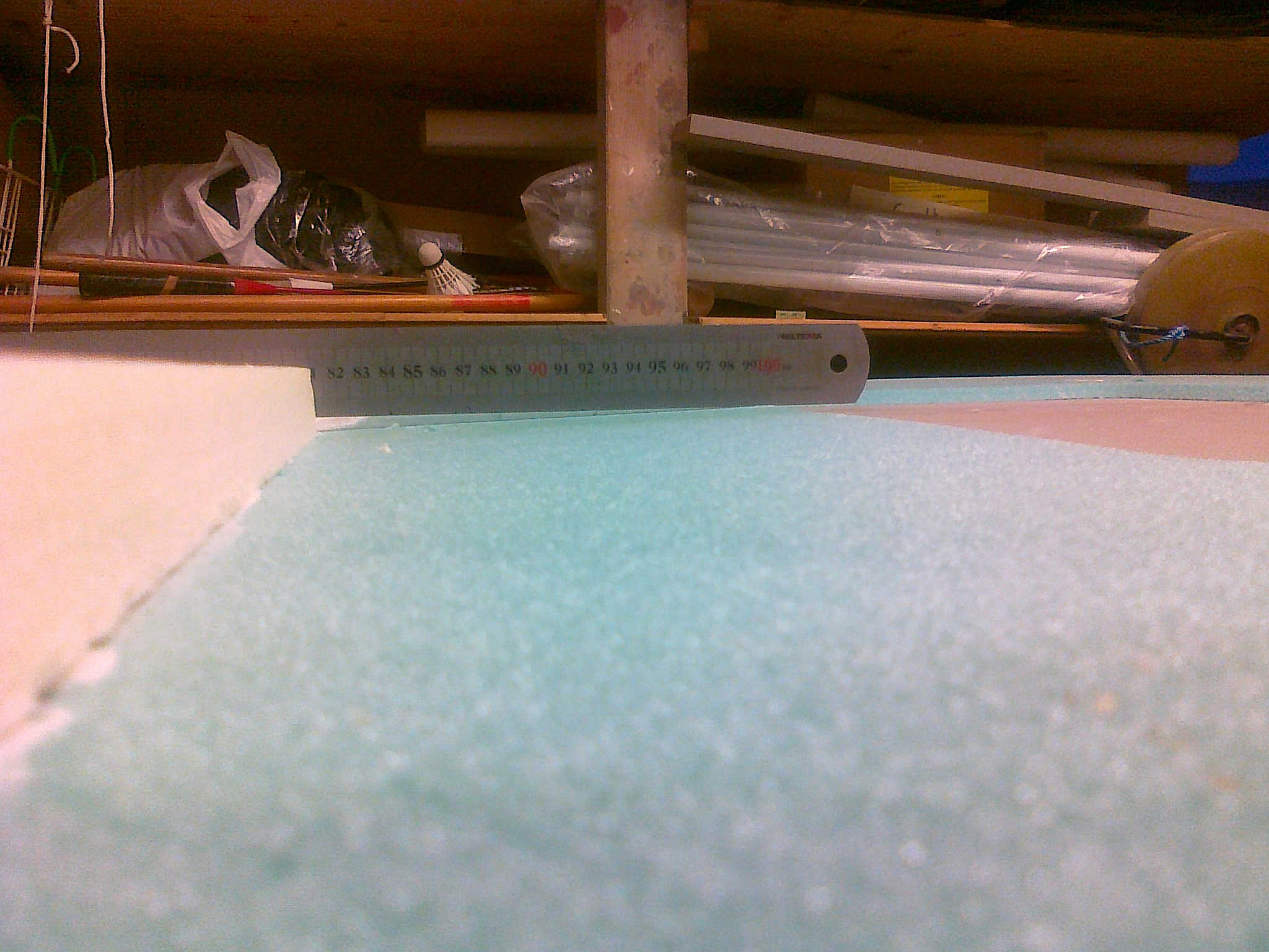
The gap is almost 6mm (1/4″). I don’t know how visible this will be when the fuselage is finished, but it’s easy to just add some more urethane in front of the existing foam and sand it down together with the other foam.
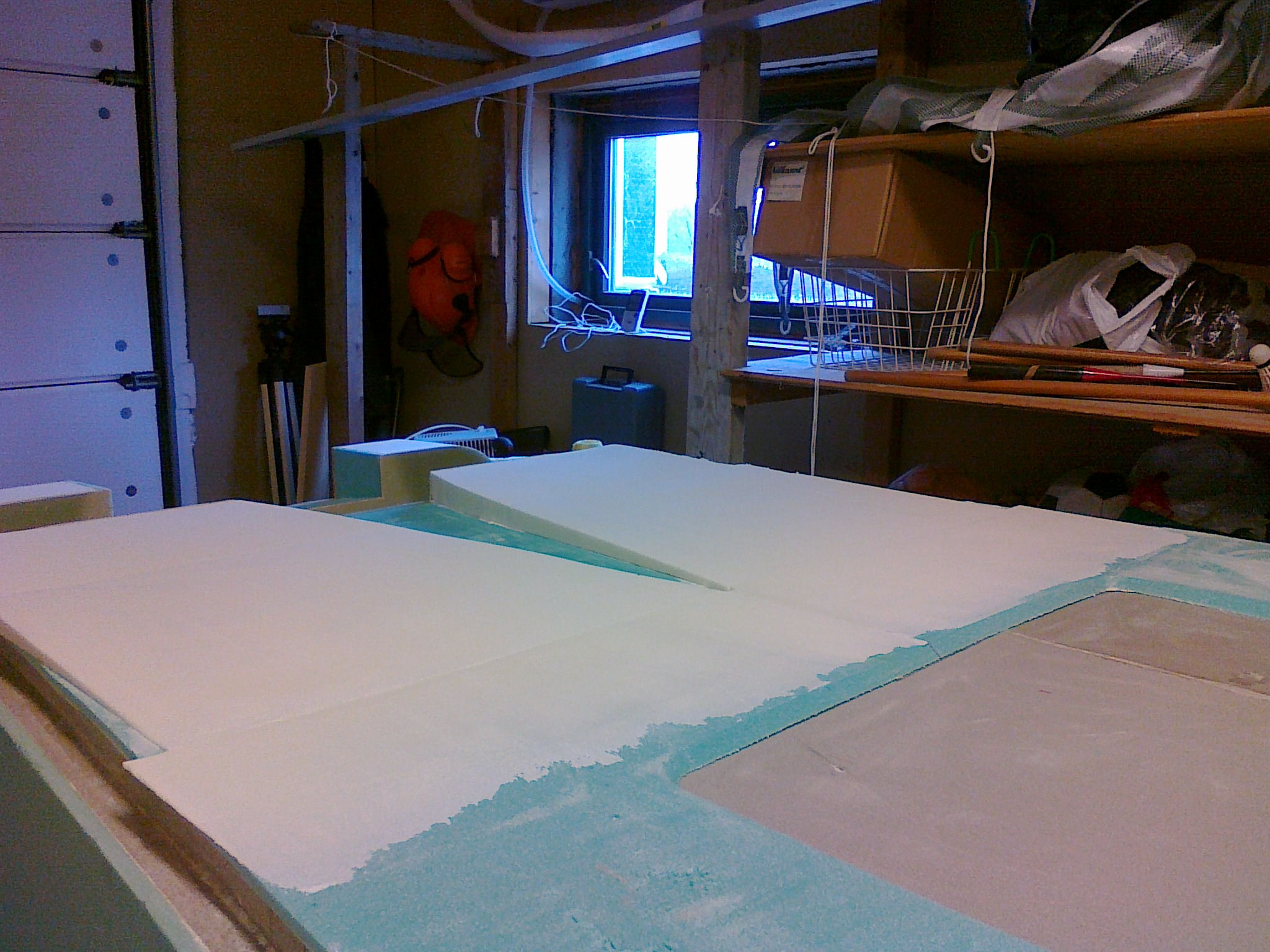
Here the extra foam is added to the fuselage and let to cure.
Started to sand the scoop. Took 20 minutes pr. side. Lots of dust! Had to wear a dust-mask and use the vacuum-cleaner often. Here the first side is finished.

Seen from the front. the transition between the fuselage and the scoop is perfect – thanks to adding the extra foam.

Compared to the picture above the gap has disapeared totally.
The bottom will now be totally flat from the point where it used to go down. No dip at all. This fix has now been implemented in the Cozy-FAQ so that new builders can be aware of this.
Here the scoop is ready for glassing. Took 45 minutes to sand the whole scoop. Not bad! Only hand-sanding using the plans method.

And finally the inside of the scoop is glassed with 2 plies of BID. The white speckels are mainly the micro I used to fill the voids in the foam. However – there was some air-pockets in this layup. I fixed this by drilling small 1.5mm holes through the glass and inject raw epoxy with a thin syringe. Worked very well!
A tip: I made micro-corners between the walls and the bottom of the scoop to get the glass to lay down properly. This is no problem for the functionality of the scoop. The important thing is that the corner between the fuselage bottom (not the scoop-bottom!) and the vertical walls of the scoop are square. They will be this when the bottom is glassed later on.