
I’m going to use an electric actuator to extend and retract the landing-brake instead of the manual mechanism in the plans. I have also increased the length of the hinge from 10″ to 16″ based on several builder’s experiences. The latter mod is not neccessary, as several 100’s fly with the original length. The reason for extending was to make it stronger, but since no one has ever had a failure here, there is really no reason other than making the flap itself a bit more easy to cut.
Oh – one thing to mention: The plans material-list calls out for a P6-hinge. This is wrong, as the plans refer to a P5-hinge. The only difference is the width. P5 is 1 3/4″ wide full open, while P6 is 2″ wide. I have the P6-hinge and will just adapt the building to the fact that the hinge is slightly wider.
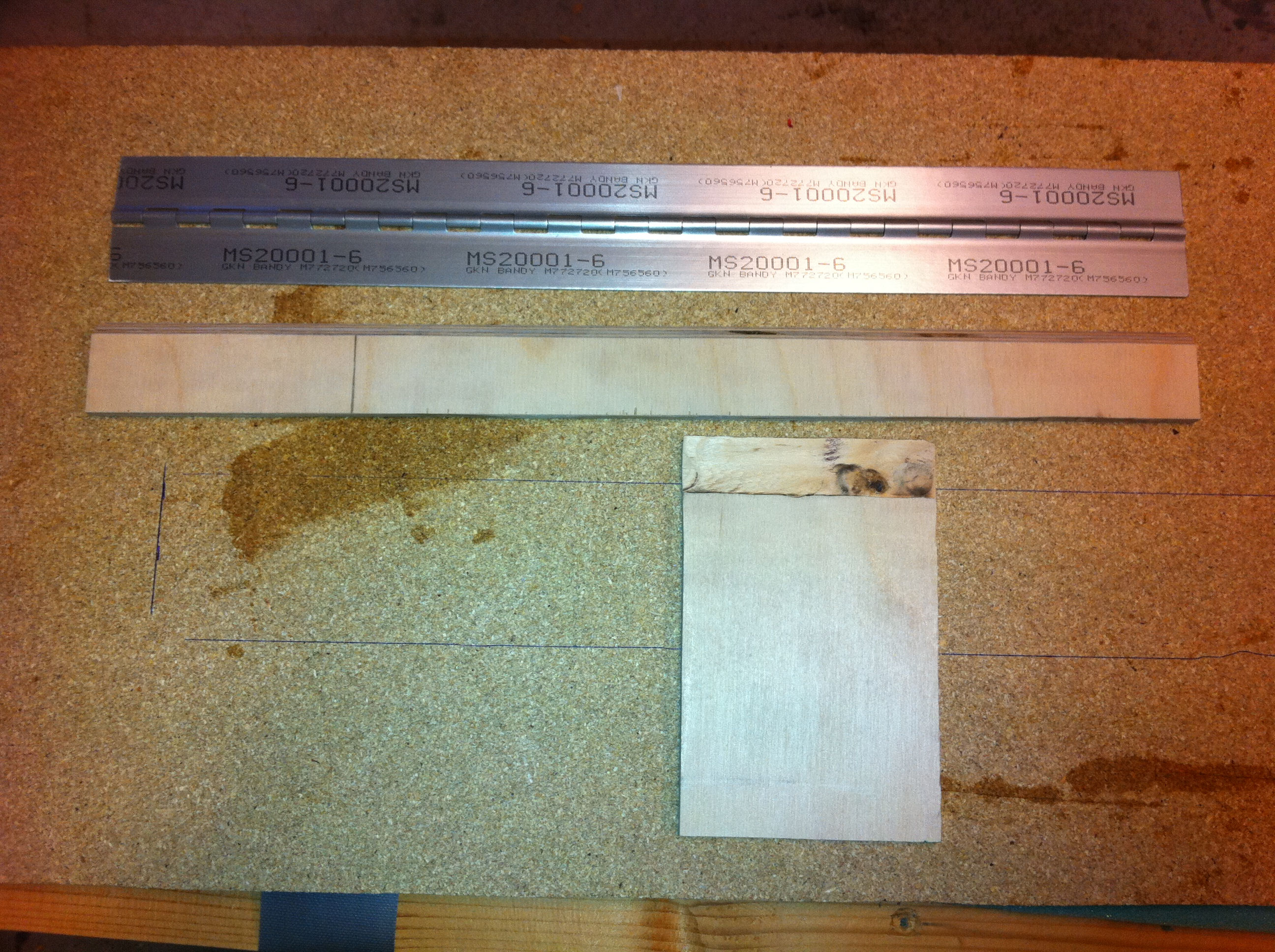
2011-07-11: The first thing to do is to make a couple of plywood-parts LB19 and LB23. I beveled the edges 45° and routed a 1/16″ deep depression in the smaller plywood-part. The hinge will be glued here and be flush with the surface of the plywood.
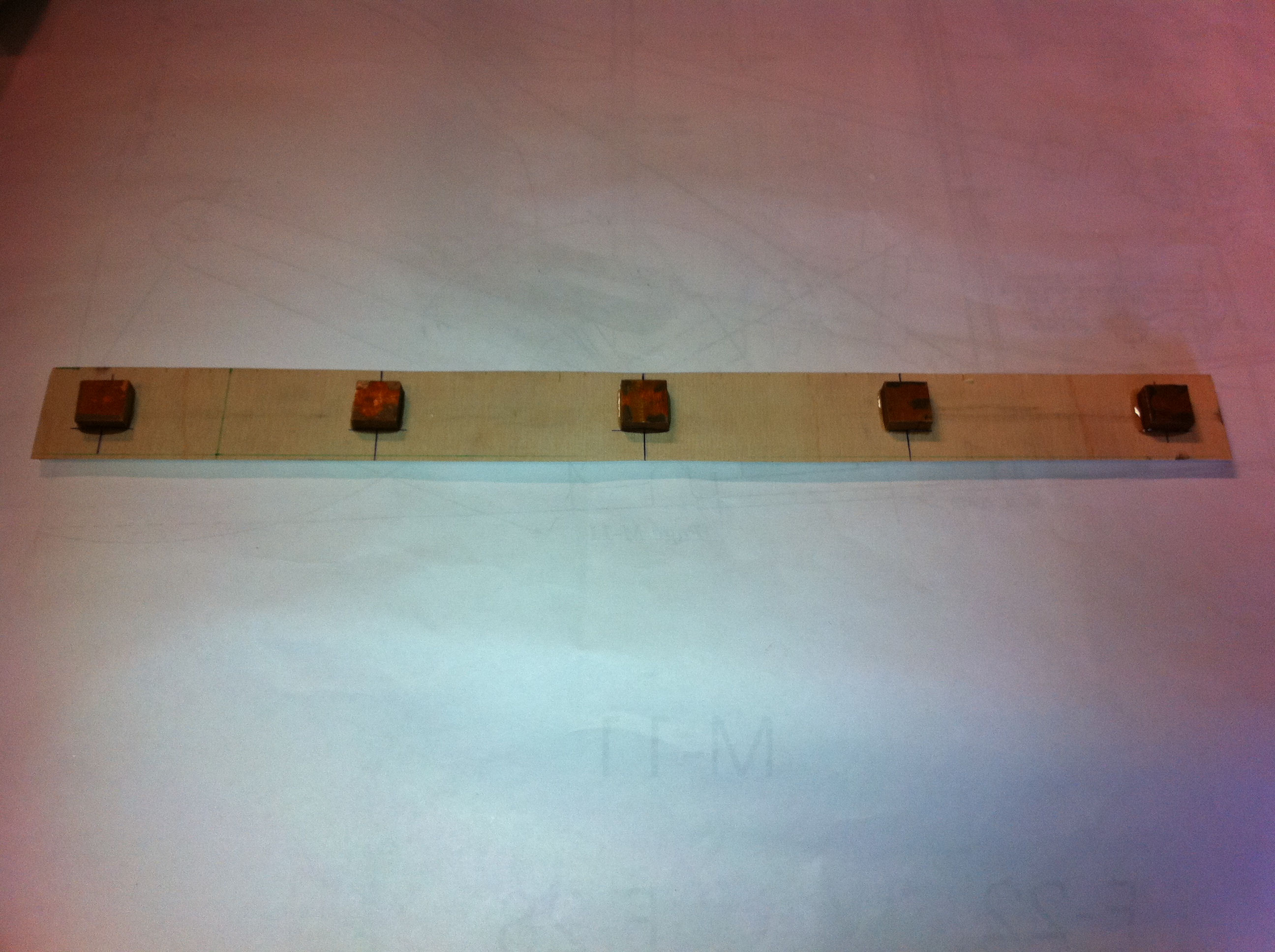
2011-07-12: I made 5 slugs of 1/4″ thick aluminum. Alodined and glued on LB23. The plans calls out for 4 slugs but since I made the hinge 6 inches wider I added another slug. These slugs will be drilled, tapped and used as fasteners for the landing-brake.
2011-07-12: I routed a 1/4″ slot for the LB23, and routed slots for the alu-slugs.
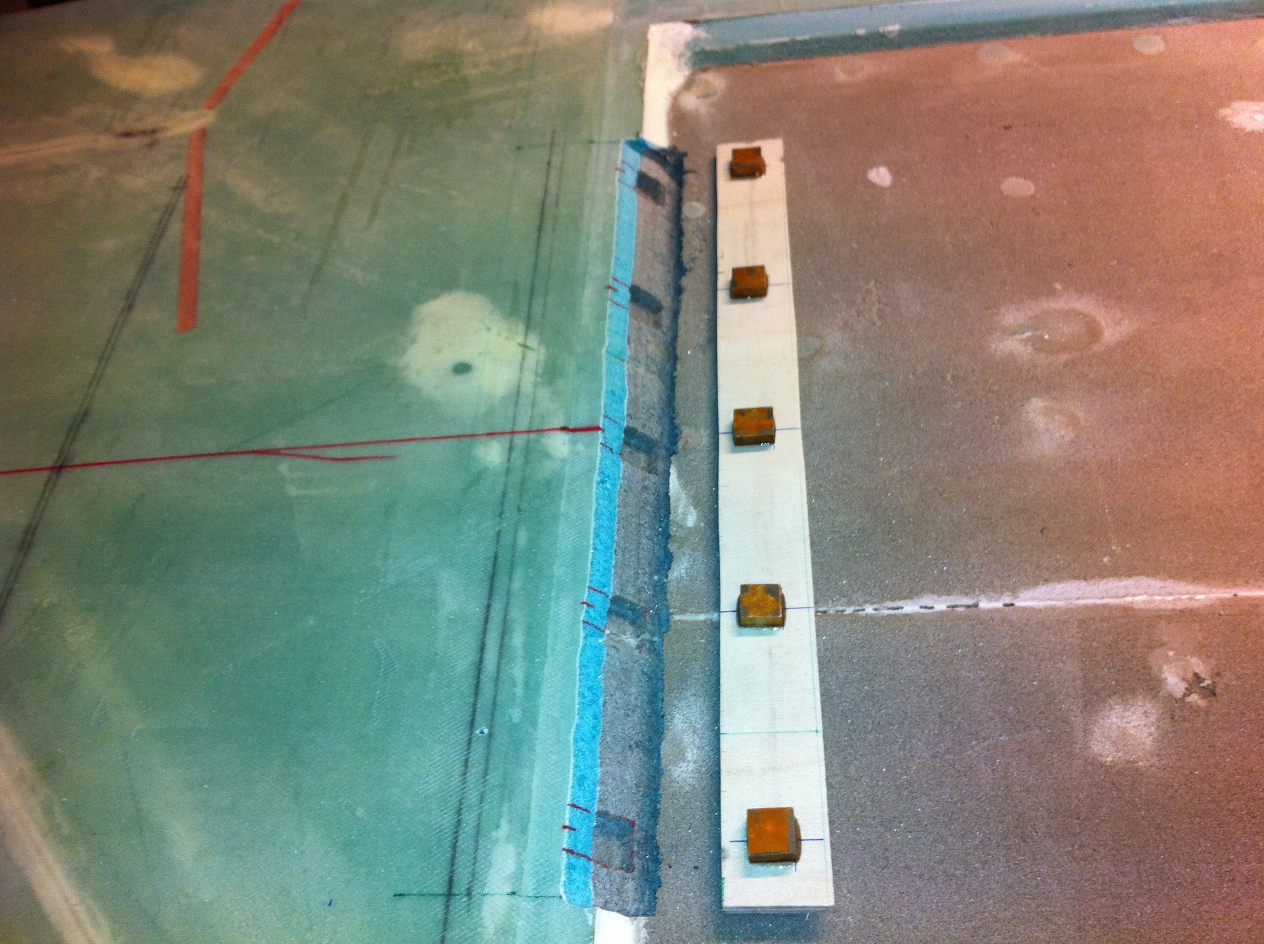
2011-07-12: LB19 is glued to the hinge. LB23 is tacked to the hinge as well. The plans calls out for three temporarily alu-shims between the hinge and LB23. As suggested in the community I used three plies with duct-tape instead. I used double-sided carpet-tape to fasten the hinge to the duct-shims.
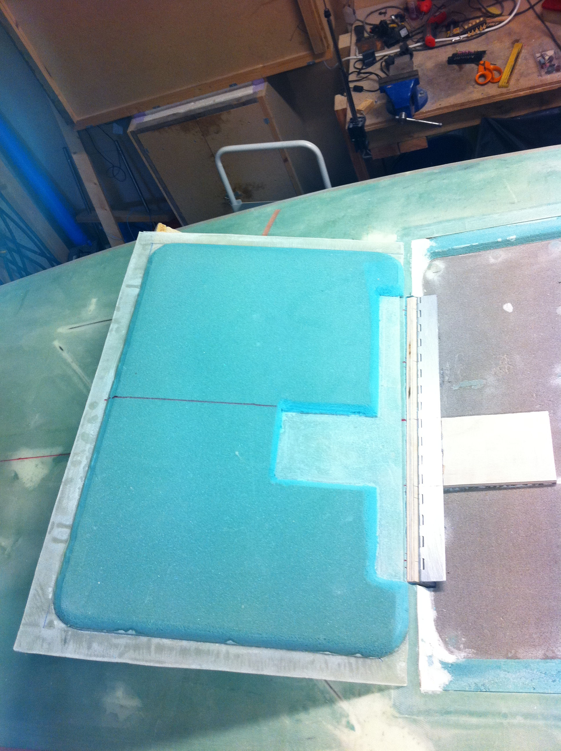
2011-07-12: I measured the position of the hinge and LB19 onto the landing-brake and removed the foam down to the glass. I also removed some mm’s of glass where the hinge will meet the brake.
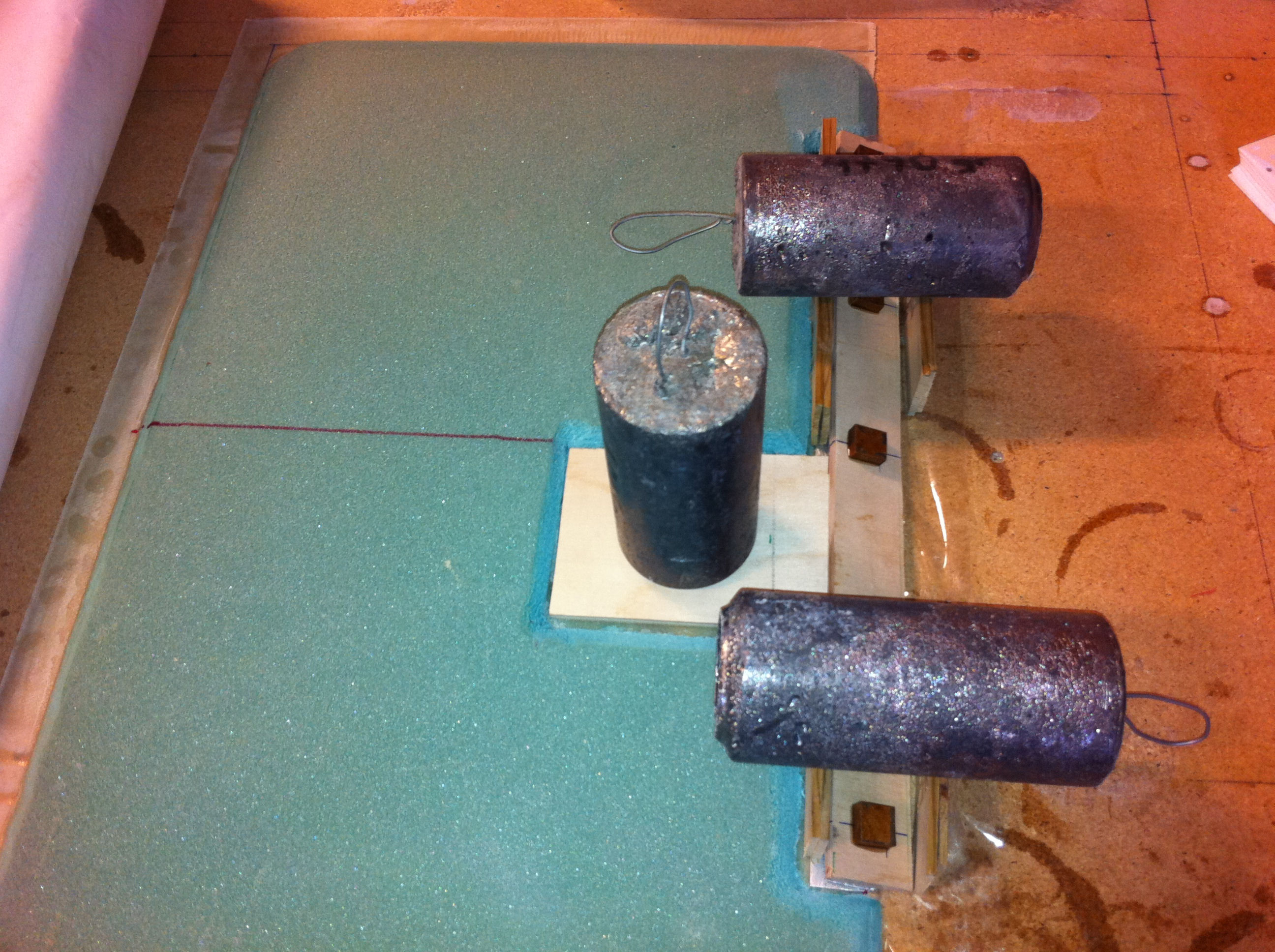
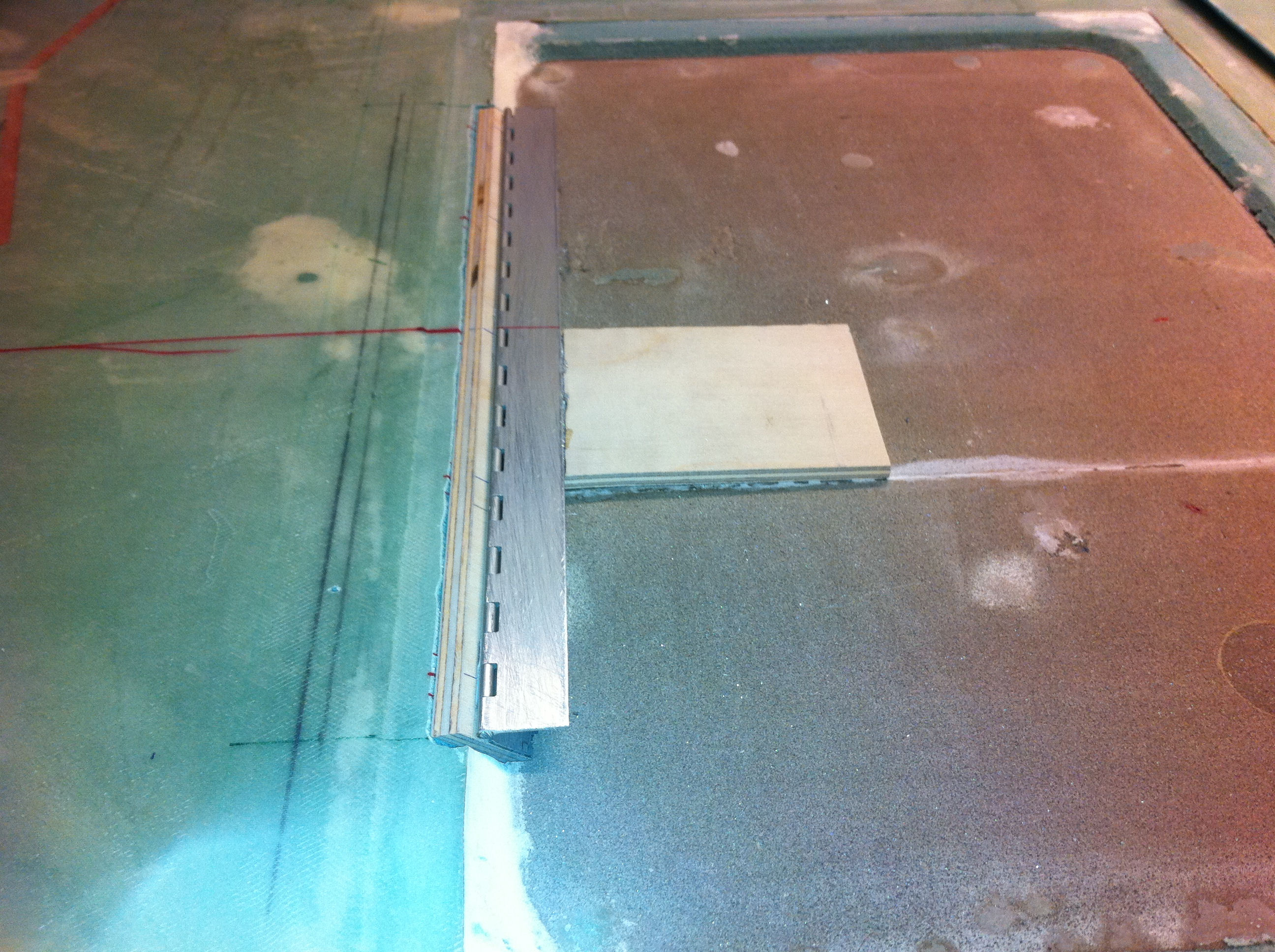
2011-07-12: The hinge are hopefully placed correct, and together with LB19 floxed to the landing-brake and set to cure.
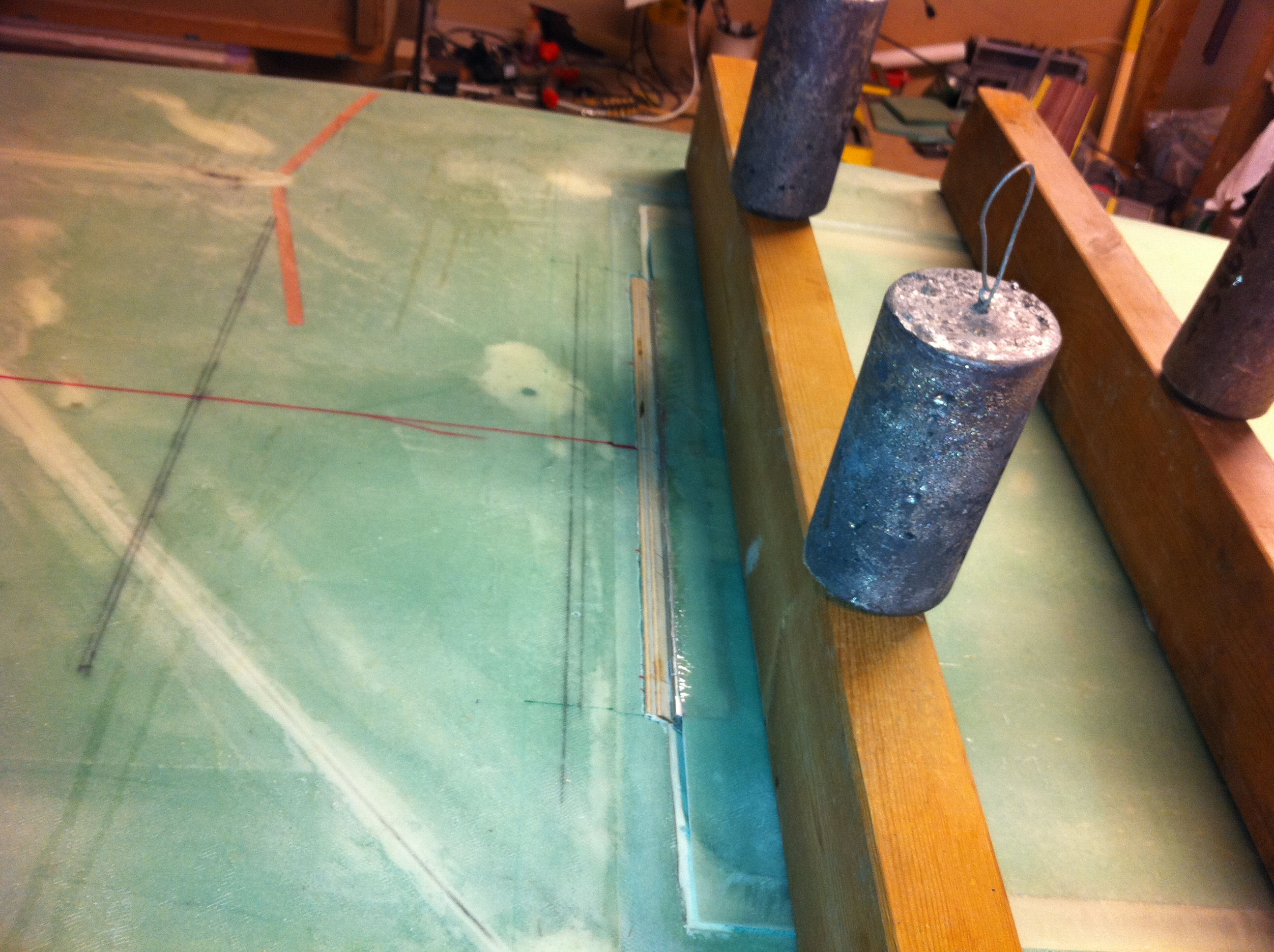
2011-07-14: Two long 2″x4″ are bondoed to the landing-brake. LB23 is microed into the slot and set to cure.
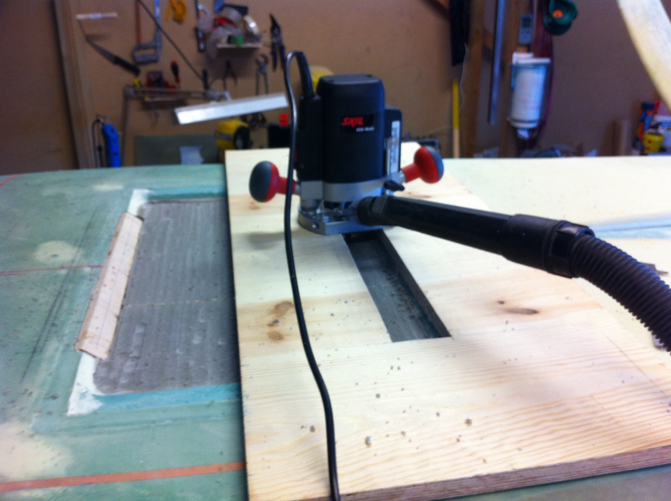
2011-07-25: I need to remove 1/8″ of foam in the recession for the LB. I decided to use my router for this. The vacuum-cleaner took care of most of the dust. I then sanded it smooth.

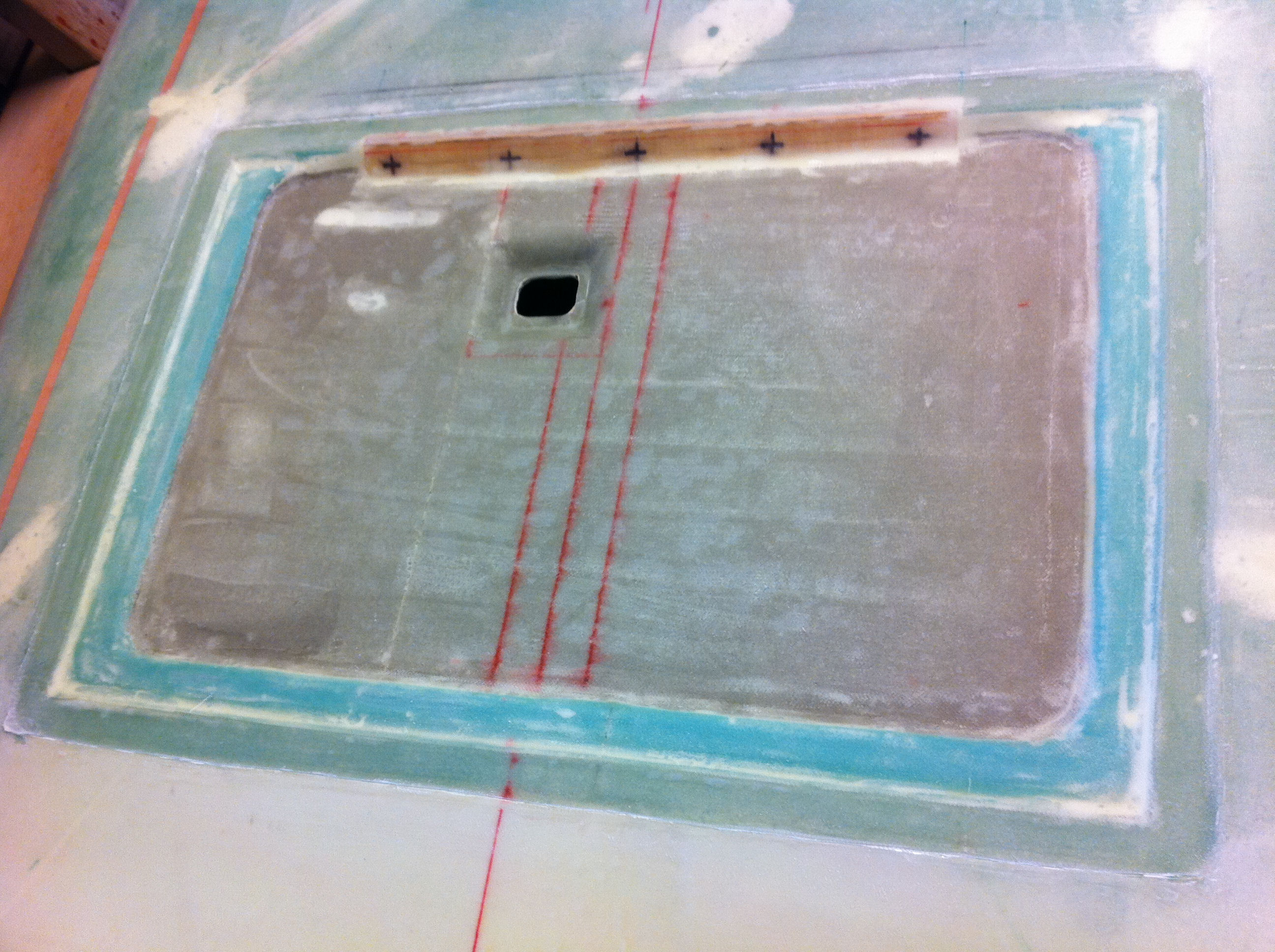
2011-07-26: Since the plans describes the manual lever to deploy the landing-brake, and I will use an electric actuator, I need to figure out where the hole in the fuselage will be. I read some other builder-logs and found some examples that I followed. If the hole is misplaced it will be a small job to open it up in either direction. The red lines are the centerline and the heat-duct. The left grey’ish line is the junction between to Divinycell-sheets.
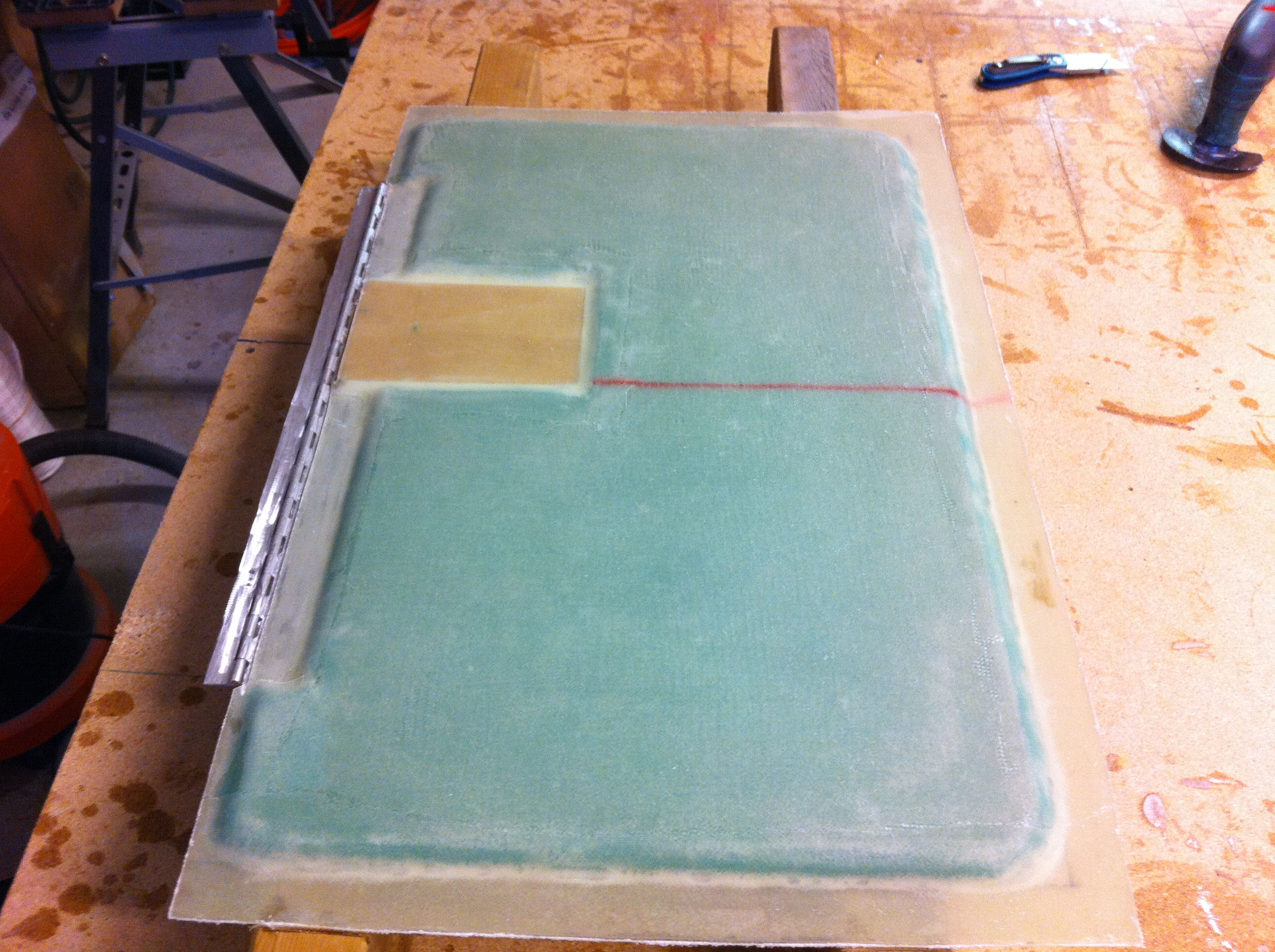
2011-07-28: The recession is glassed with 2 BID. A third ply of BID is placed over the depression for the actuator-hole and over LB23 extending 1″ around. I have cut clean the glass and sanded the edges.
The outermost recession made by Duct-tape in an earlier chapter was to provide room for the 2 plies with BID – to avoid a bump in the fuselage. Looks like my Duct-tape is slightly thicker than what Nat Puffer used. I still have a small recession after glassing. I will fill this with micro when I finish the tub, so it’s no big deal really.
2011-07-29: The LB was then prepared for glassing with 3 BID. After cure I cut clean the glass. The plan calls out for me floxing the hinge to the fuselage after only 4 hours of curing. I opted to skip that and let the LB cure completely before I moved it.

2011-07-29: Still with the 2″x4″ attached I have floxed the hinge to LB23.
I covered the hinge with clear packaging-tape to make it easier to pop loose the hinge. Many builders have given this advice since the brake has to be removable. The plans are somewhat vague around this point.
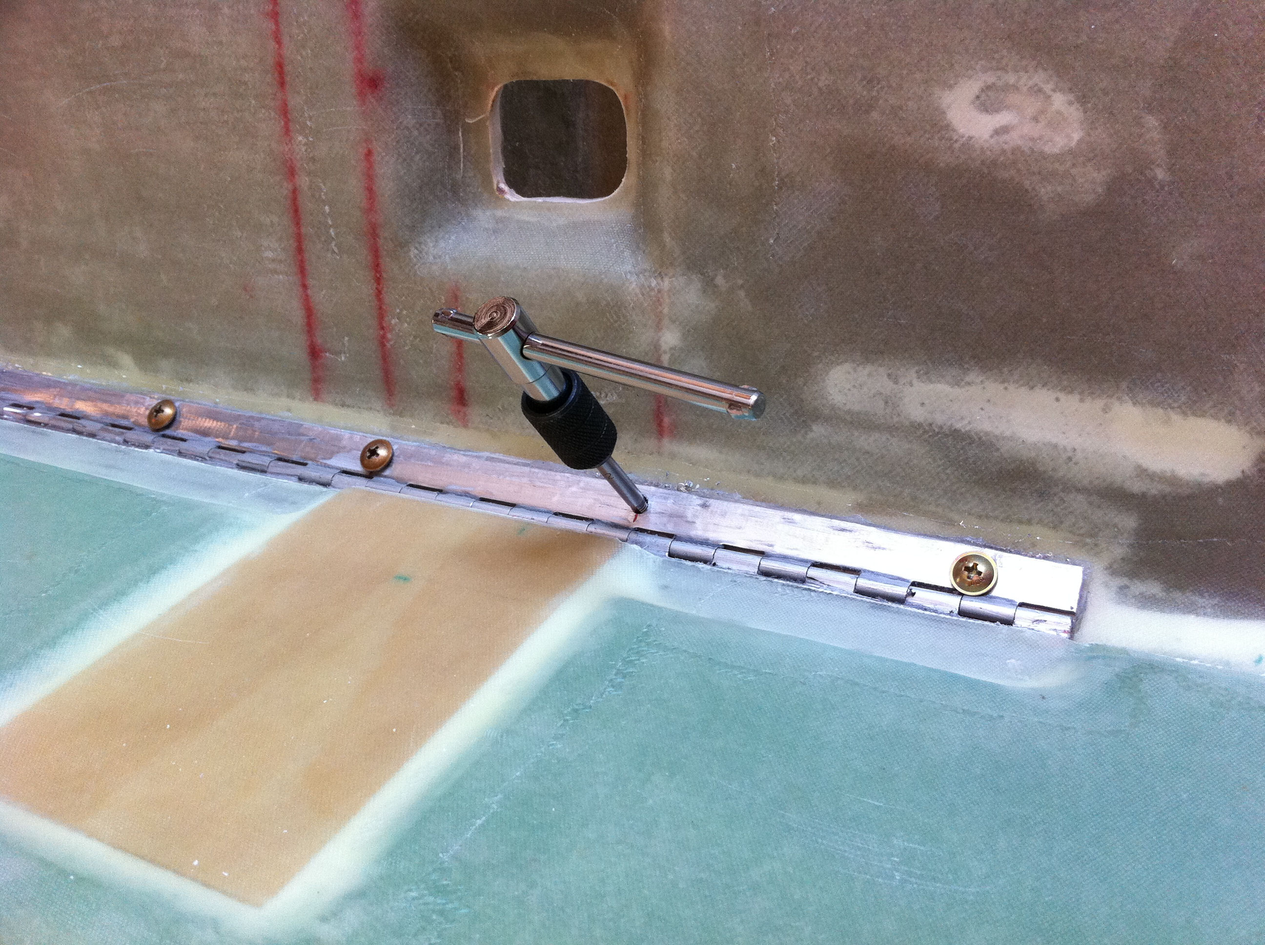
2011-07-30: I removed the 2″x4″‘s and opened up the landing brake. I drilled holes through the hinge, LB23 and the aluminum-slugs inserted in an earlier stage. I then tapped the holes and fastened the screws. It was easy to loosen the hinge from the flox, it fell off by itself when I started to drill the holes.
After that I drilled holes through the LB and the other part of the hinge to secure the hinge and the LB itself. Note: Had to use shorter screws than the plans told. AN525-10R8 instead of 10R10 and 10R6 instead of 10R8.
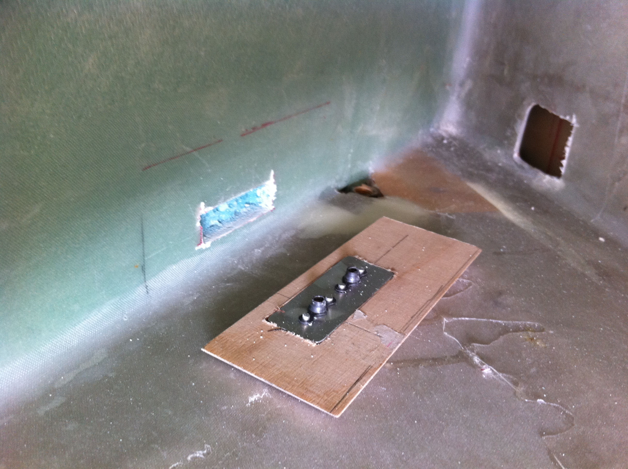
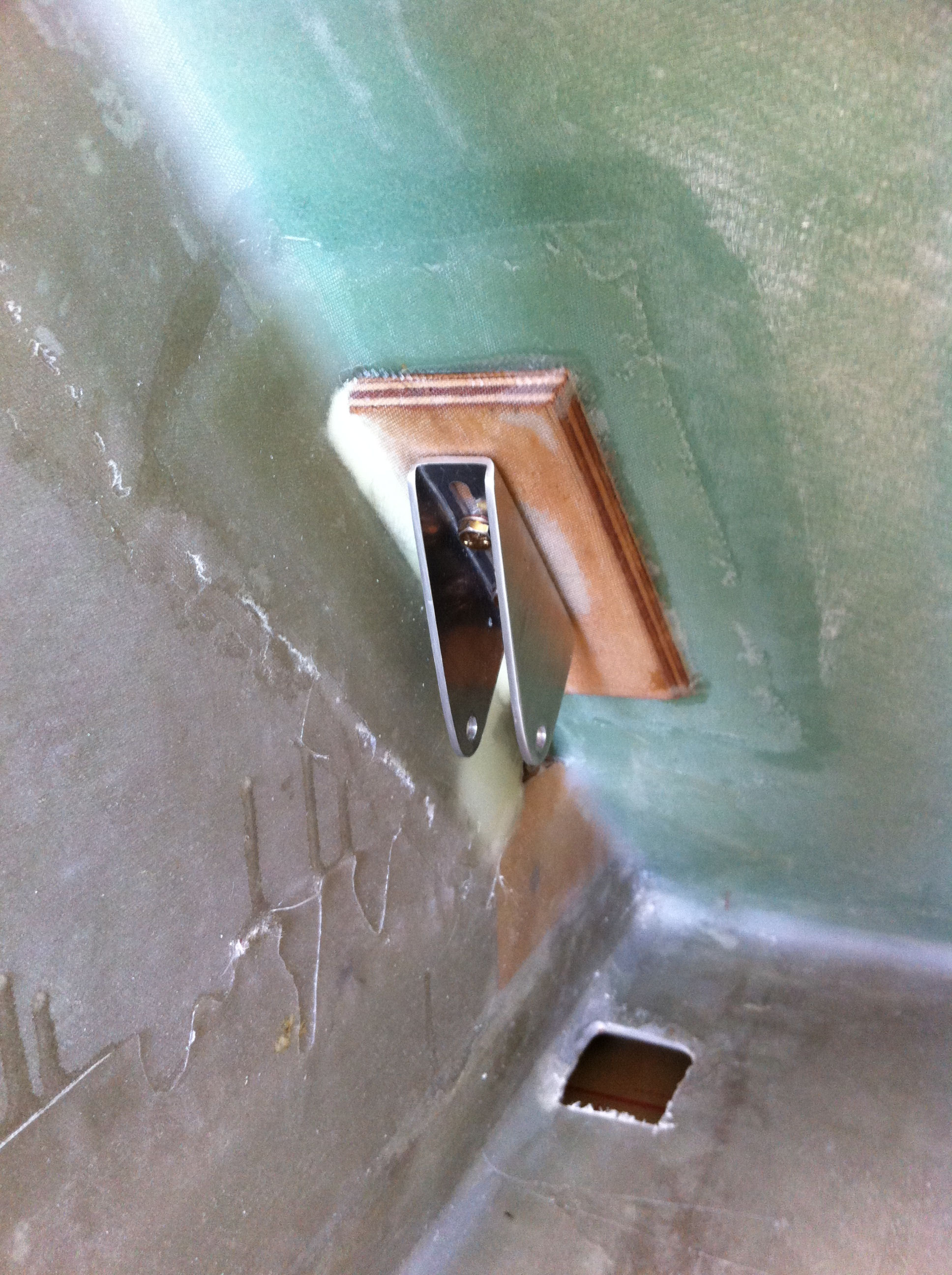
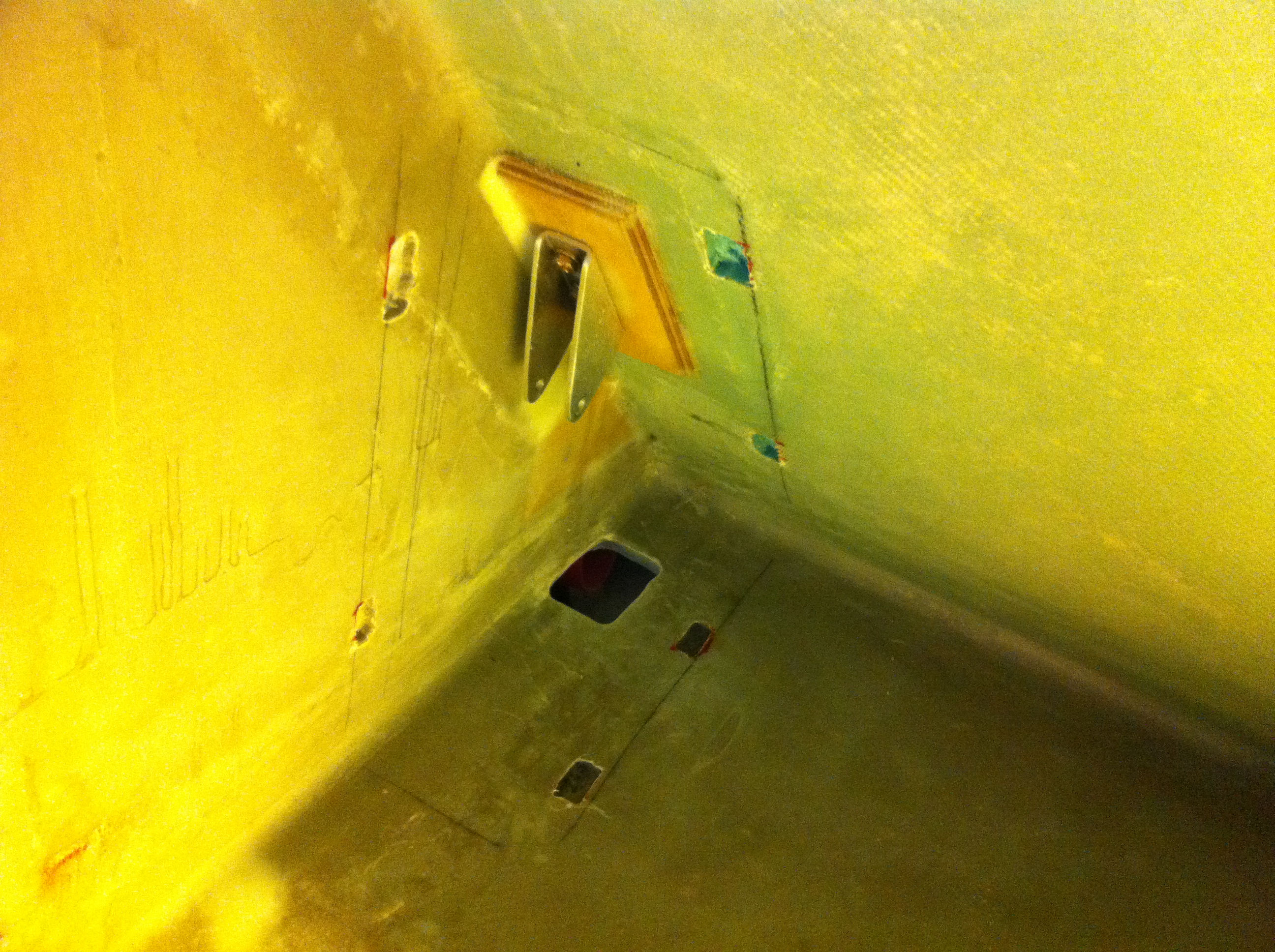
2011-07-31: Measured where the actuator would be positioned and the plywood-backplate that followed the LB-kit. I then floxed the plywood in place. I had to cut a hole in the glass to make room for the nutplates. This is pr. plan for the electric landing brake. Note that I also have cut the hole for the actuator-arm. It didn’t quite match the first hole I made so I had to make it a bit longer. You see the rough edge – I haven’t yet sealed the cut-out. This picture is taken with the tub resting on its side. The seatback is the vertical part here.
2011-08-01: The tub is right side up and I have covered the floxed plywood-plate with 2 BID overlapping 1″ on all sides. I have temporary mounted the bracket that will hold the actuator in place.
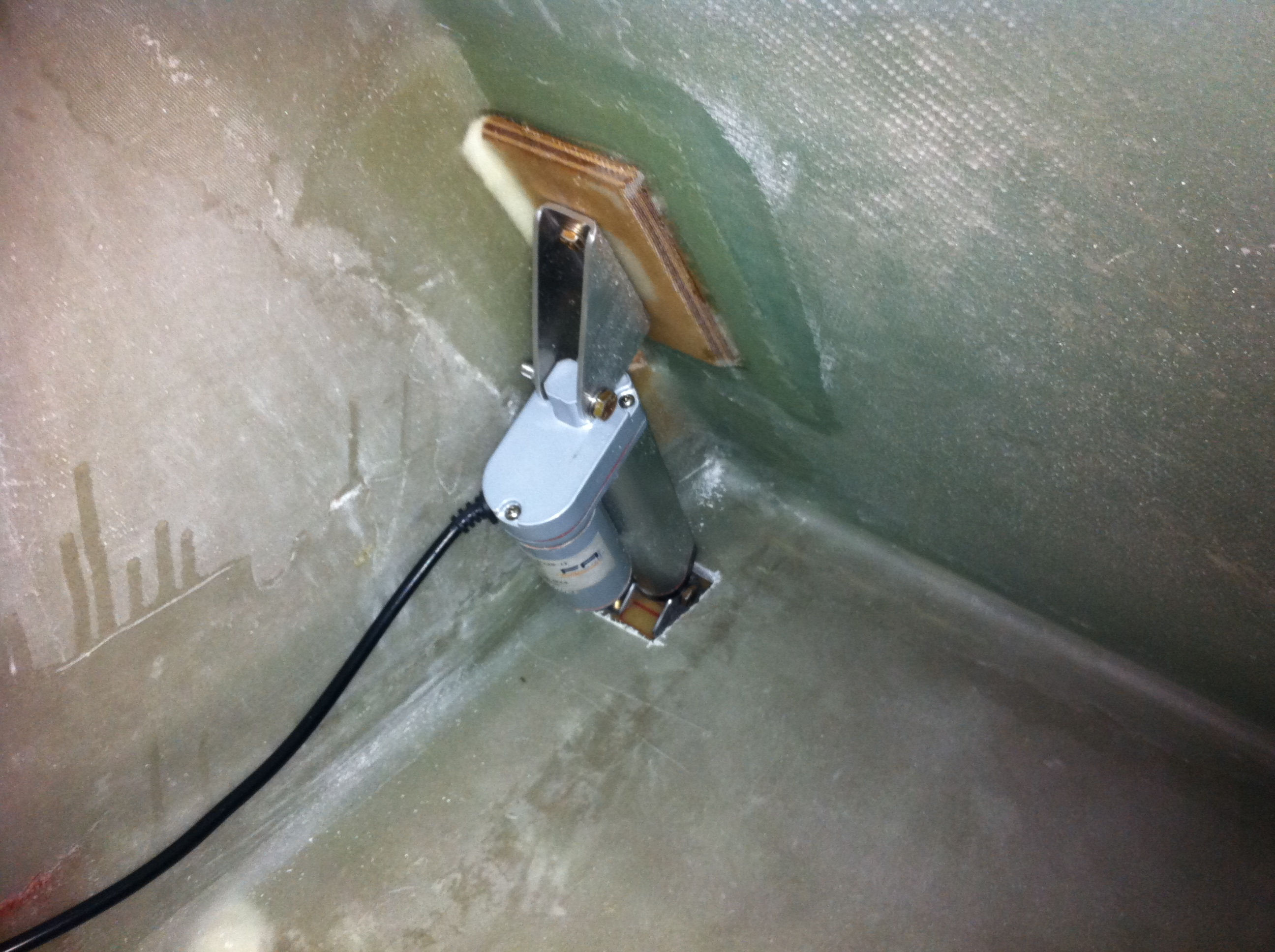
2011-08-05: The actuator is mounted and the landing-brake is ready for it’s first test…
2011-08-05: The first moving part on the airplane!

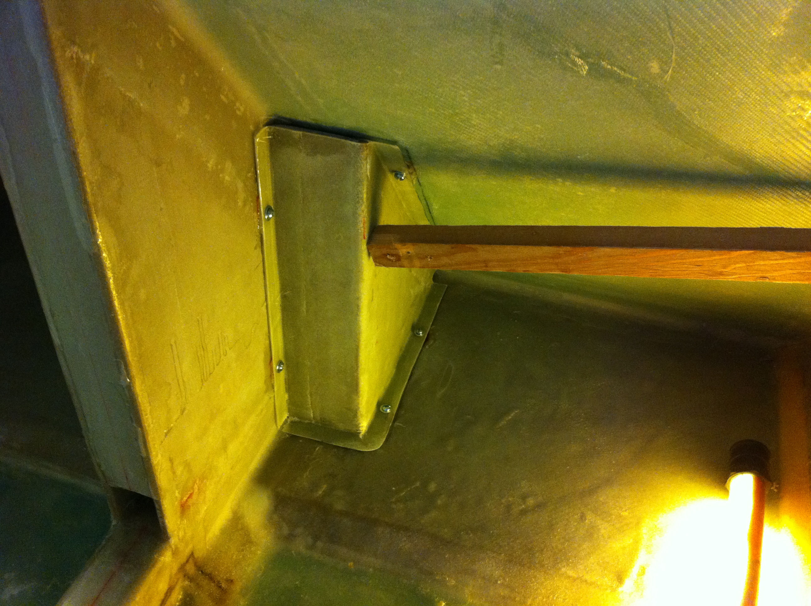
2011-08-14: To cover and protect the landing-brake actuator and the hole I made a box that fits outside the mechanism. It’s made of some scrap foam (1/4″ Divinycell) and 2 BID. It’s made similar to the heat-duct. To fasten it to the tub (it has to be removable) I make some flanges that I can fasten some screws in later. I’d wish I had fast hardener as well as the slow. I have to wait 24 hours between every layup here. Need to buy some fast next time…

2011-09-11: I made some slugs of 1/4″ aluminium – drilled and tapped them. I will flox these in place in the tub. In this picture I have fastened the slugs with screws, underneath I have some clear packaging-tape to avoid the flox to stick to the cover.
2011-09-11: I marked the positions for the slugs and routed holes in the seatback and the floor. I filled these holes with flox.
2011-09-11: Then I placed the cover with slugs in position and set to cure.