I chose the Matco-triple-puck brakes as this has come to be the standard for the Cozy MK-IV. The consequence is that the plans method has to be slightly modified. Luckily others have gone up the path for me, so I decided to follow Bernard Siu’s plans.
I started with placing the fuselage on my work-table. The table is leveled off, and I had to get some more space to work around the fuselage… it turned out to be vice to place the fuselage on the table!
Mounting the axles demands for lots and lots of measuring. I use a combination of a plumbob, a laser-level and a cross-hair laser.
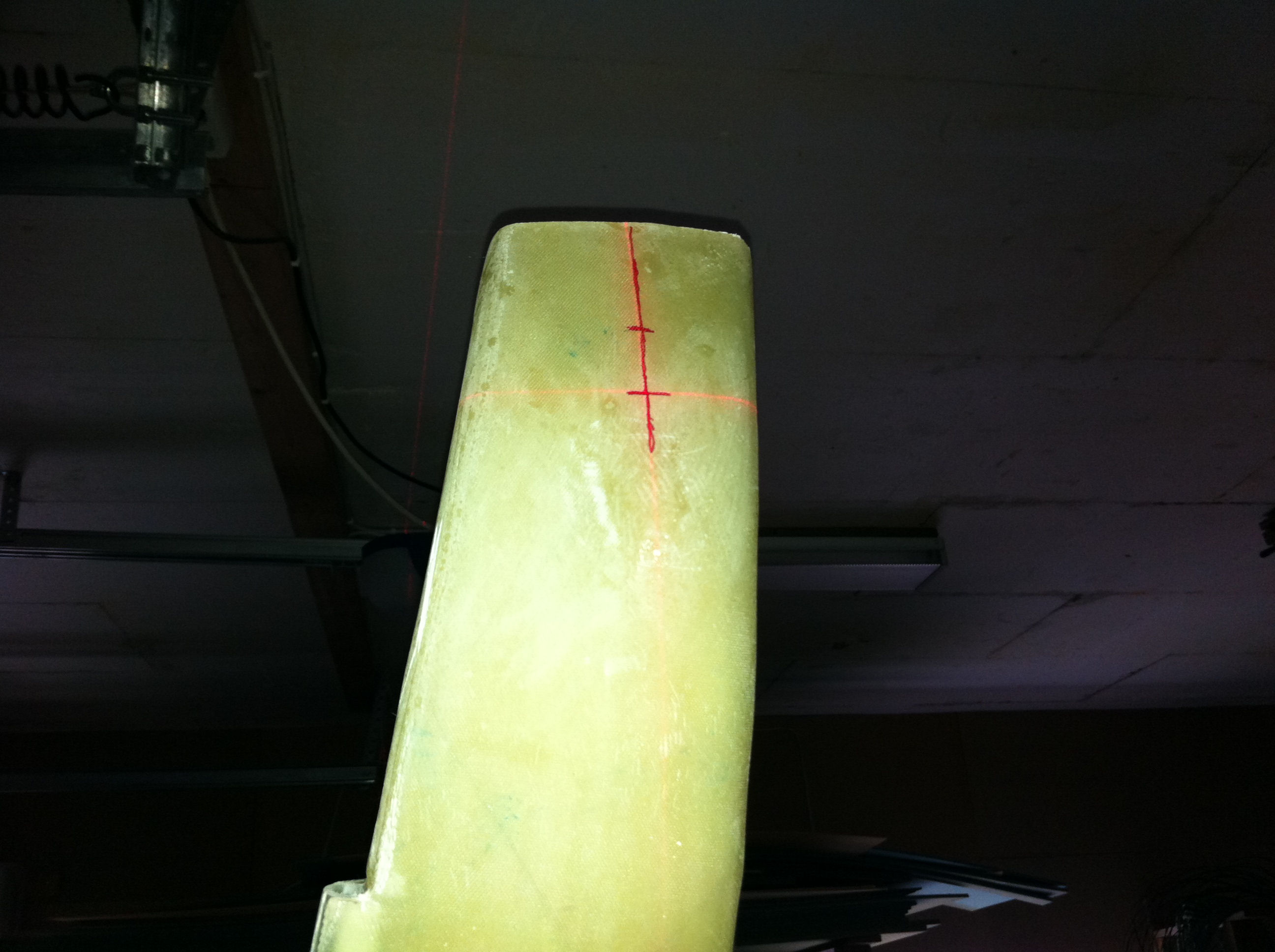
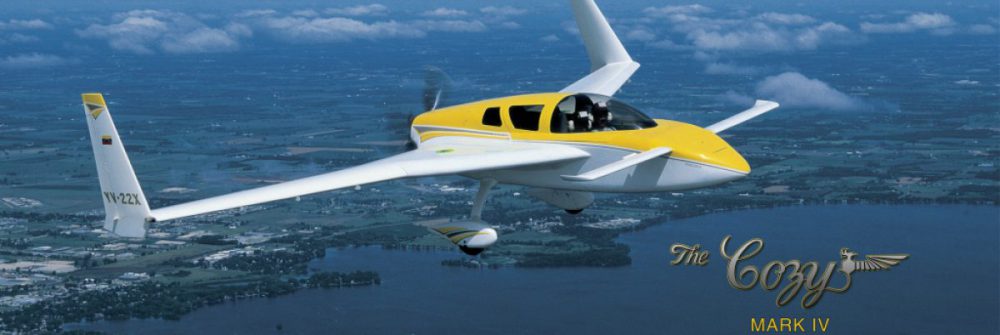
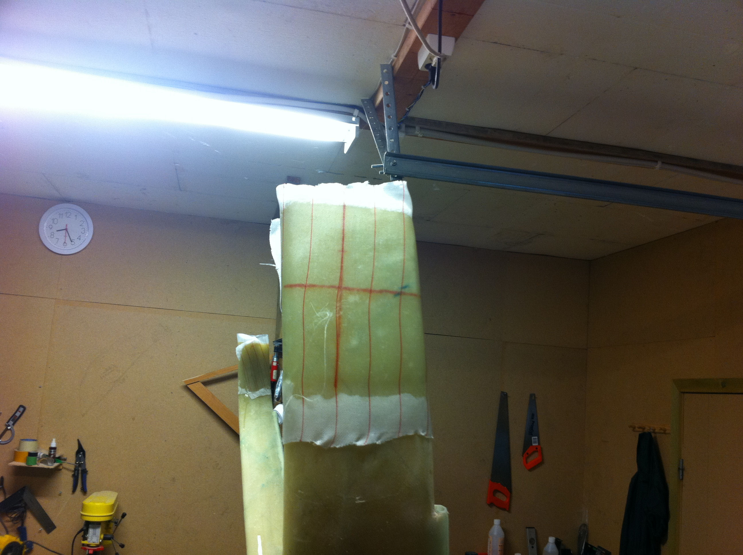
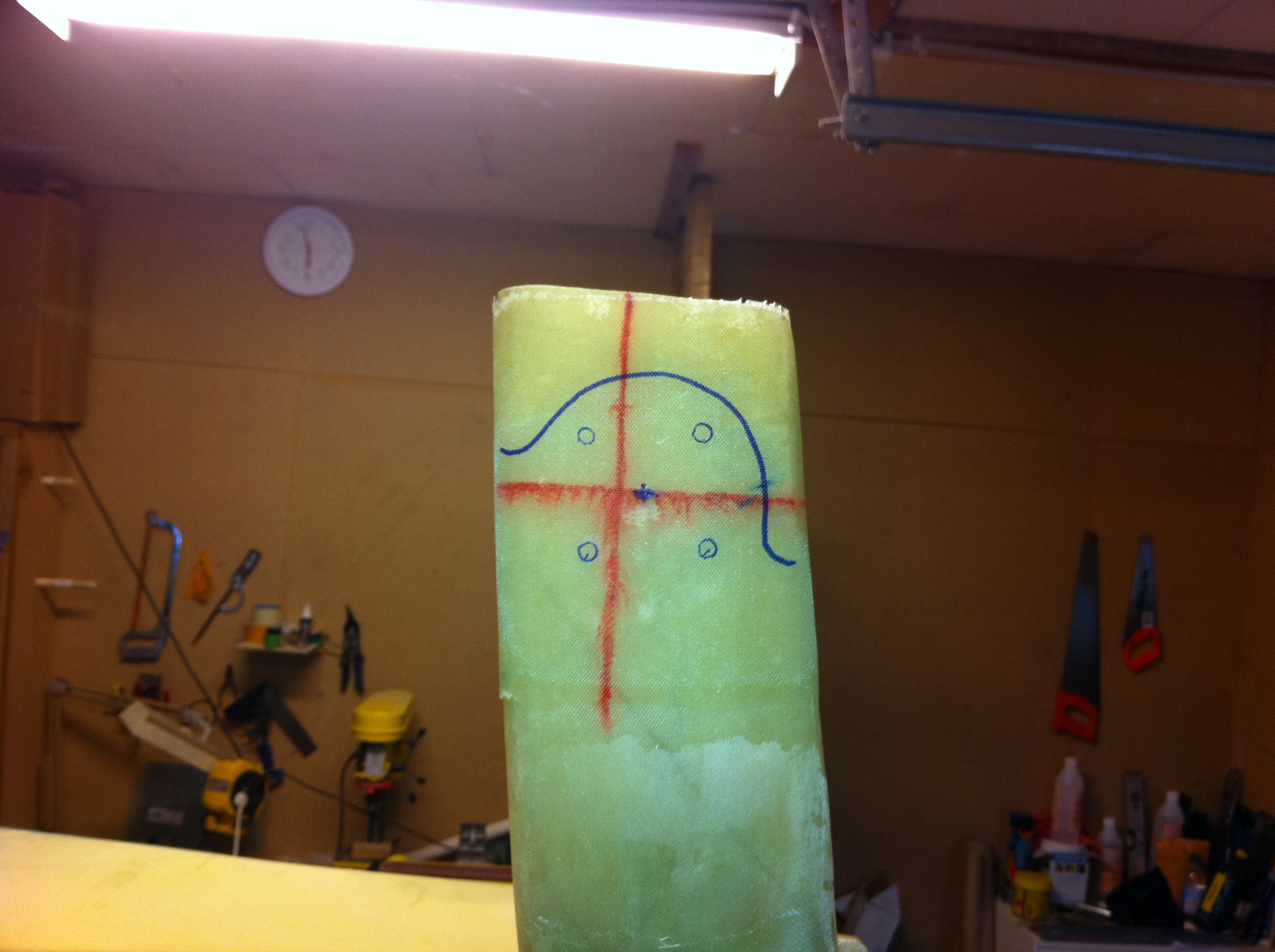
2011-07-04: Here I have marked the center-position for the axle at FS110 and WL19. I use the cross-hair-laser, not so easy to see on this picture, but turning off the light in the room makes it a bit more visible…
2011-07-04: The camera didn’t manage to capture the laser-lines correctly, but you get the idea… the cross-hair-laser is a useful tool together with the old-fashioned plumbob.
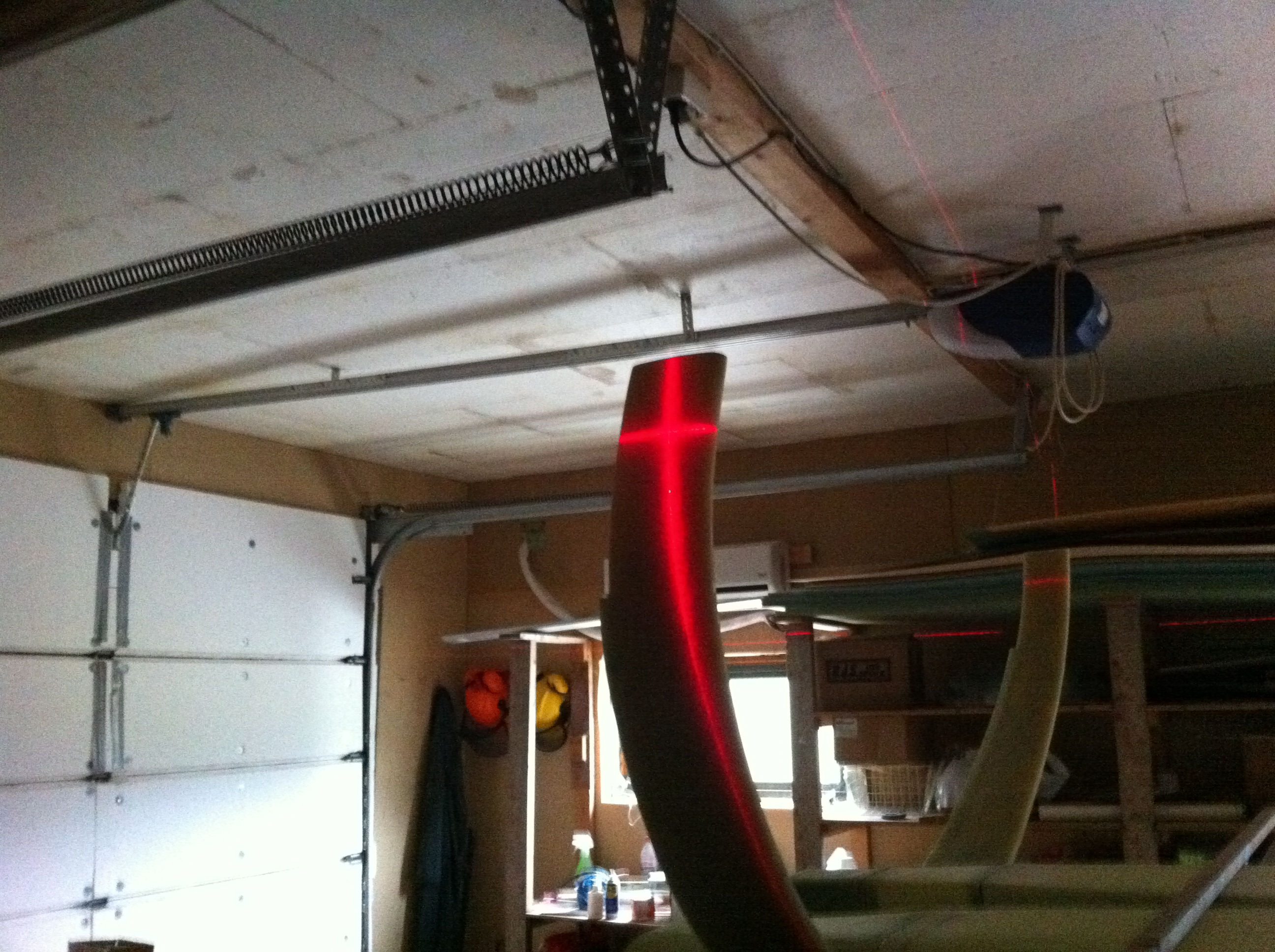
2011-07-04: Here a straight-edge is clamped at the position for the center of the axles. A level is placed ontop to be sure that both axles are placed level to each other.
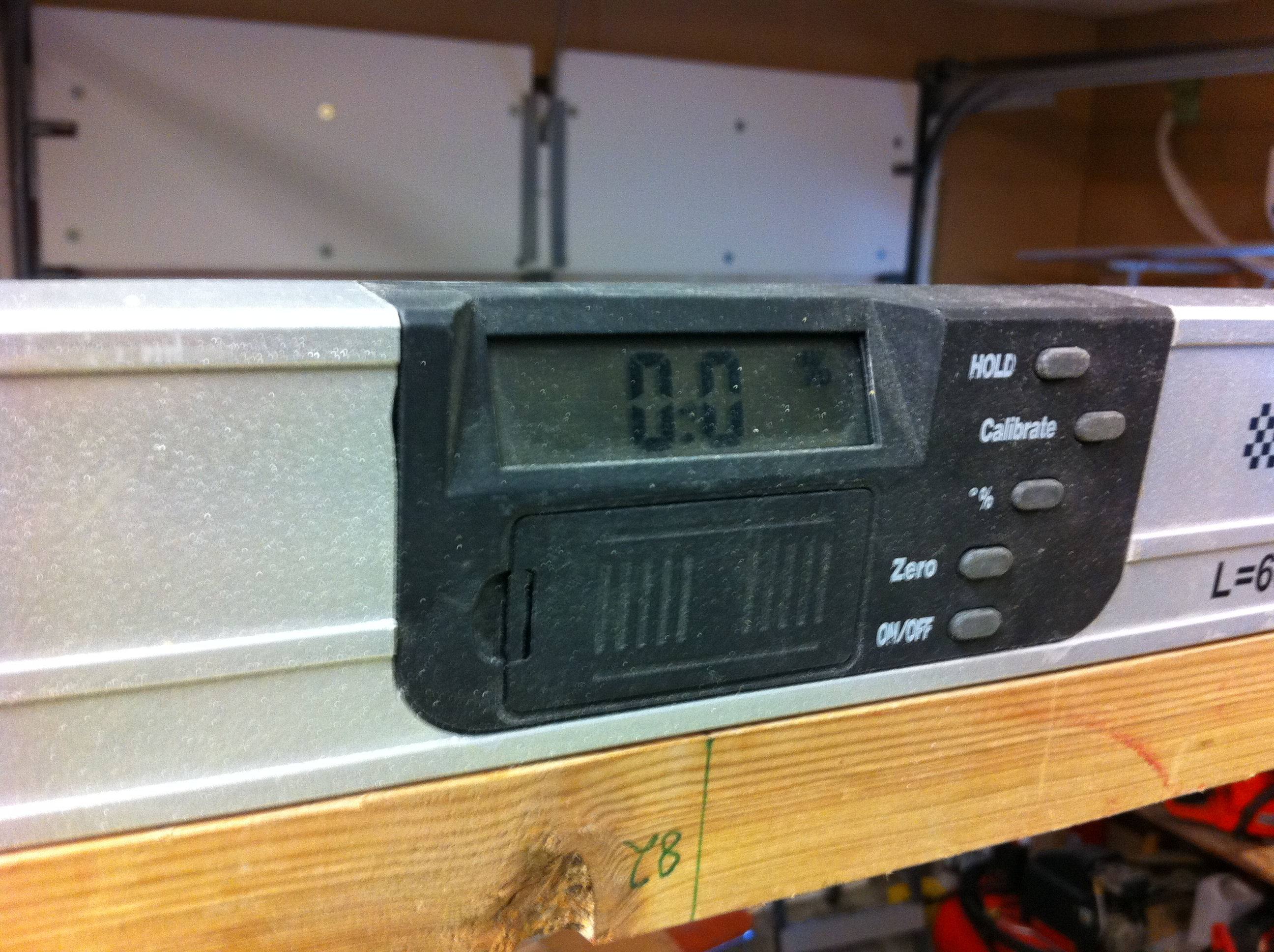
2011-07-04: The proof: 0.0 degrees… 🙂
2011-07-04: After measuring the axle-position, 3-Bid reinforcements are made at each strut-end.
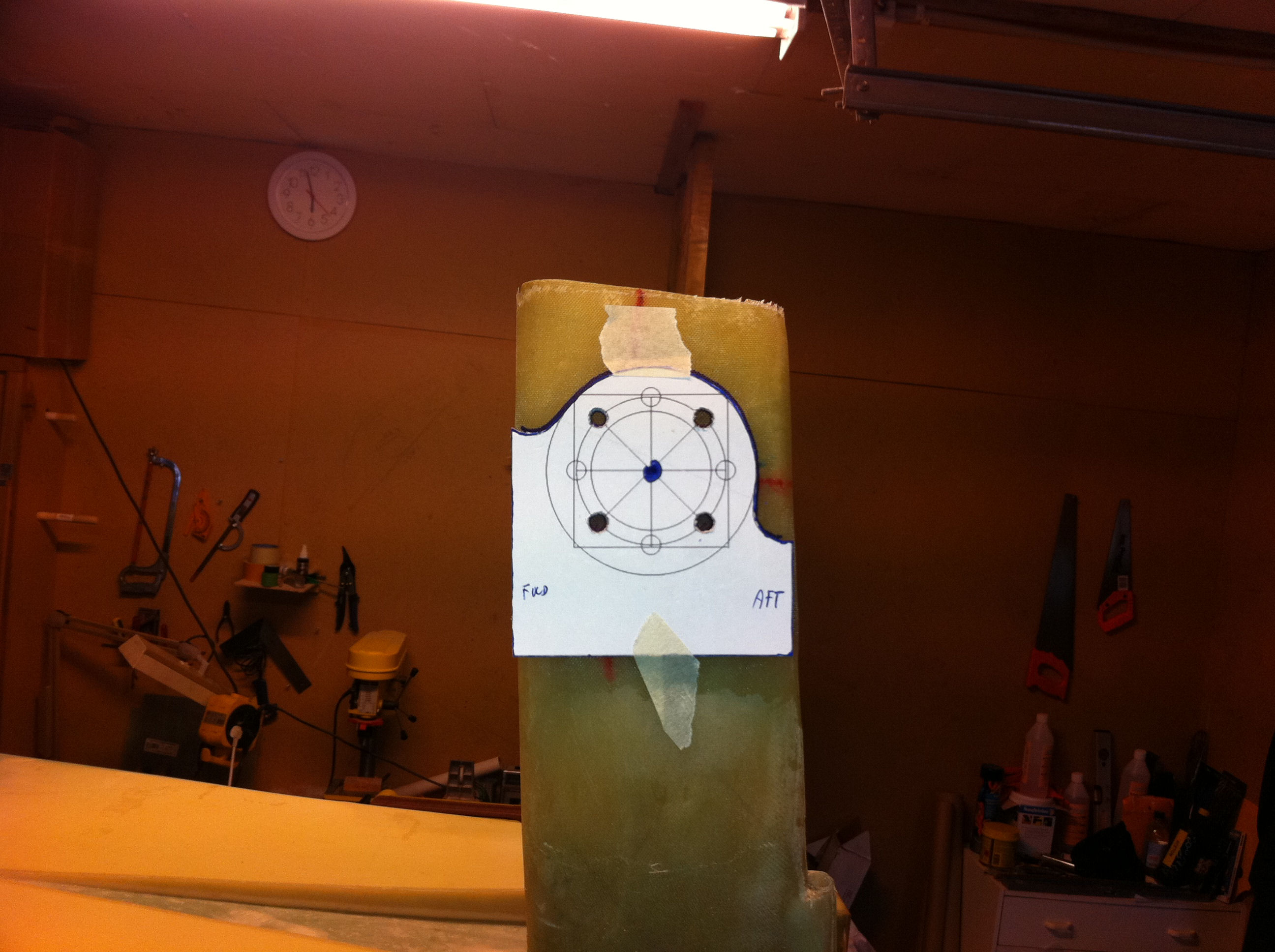
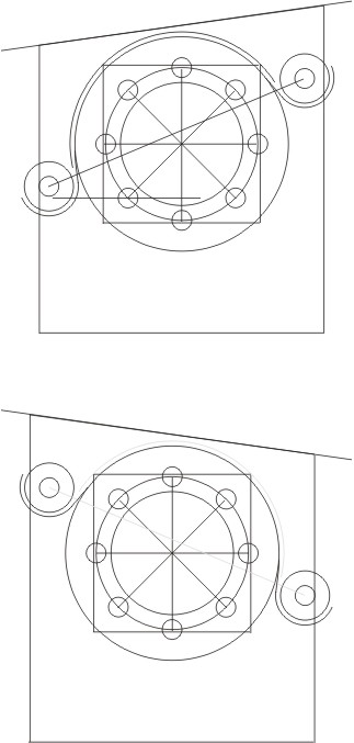
2011-07-06: The templates is made by Bernard Siu. You can download them here. They are made special for the Matco-brakes.
2011-07-06: I traced the outline and also marked the position for the holes for the axle-bolts. As one can see, the center of the axle is aprox 10mm aft of the WL110. My axles will be at WL110.3. No big deal, I’ve read about several other builders experiencing similar.
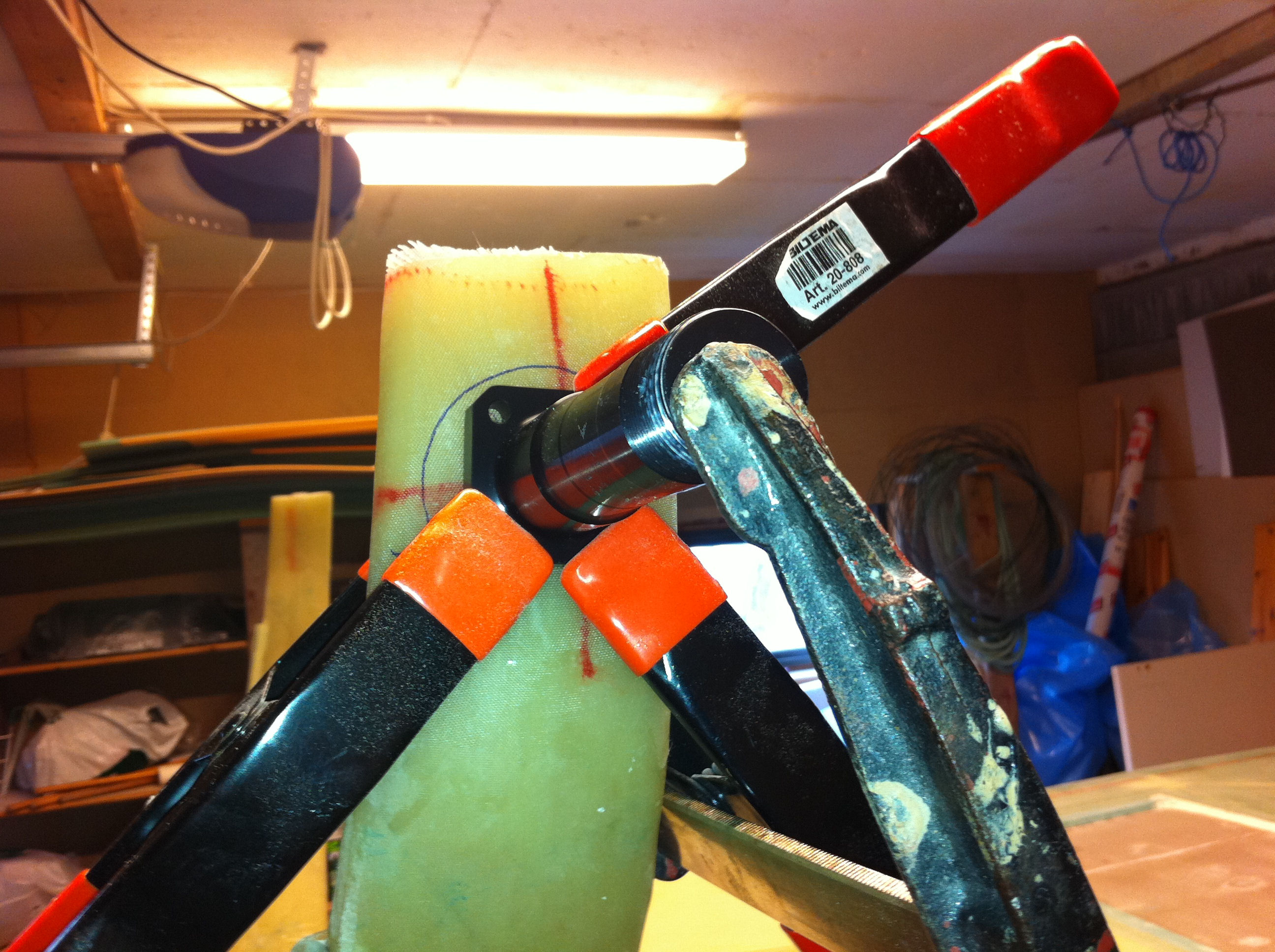
2011-07-06: Clamping the axle formly against the strut before drilling the four holes. Beware to drill absolutely perpendicular to the axle!! And you need a long bore here…
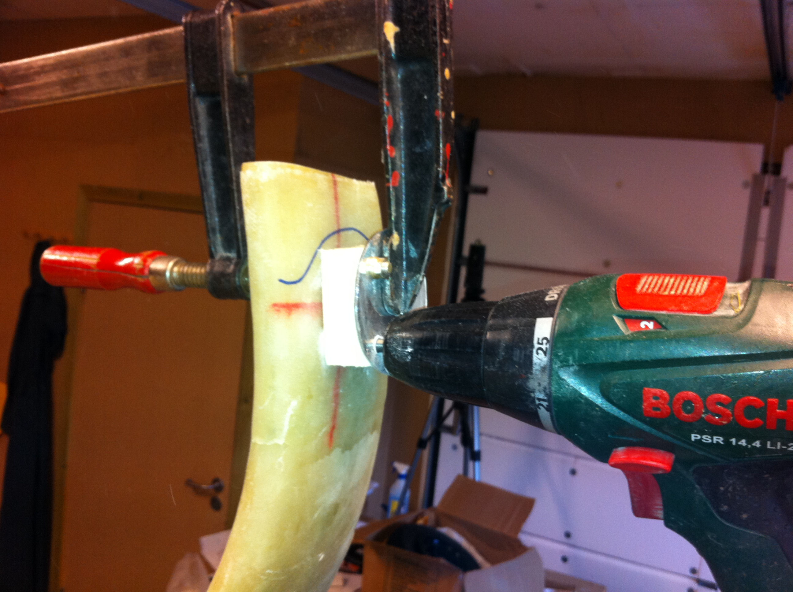
2011-07-08: I changed my strategy for the other side. Instead of using a long bore I made a jig of some wood and used this as a guide for my normal drill-bit. Nevertheless I had to trim the holes a bit to get the bolts to slide through the landing-gear, the axle and the brakes.
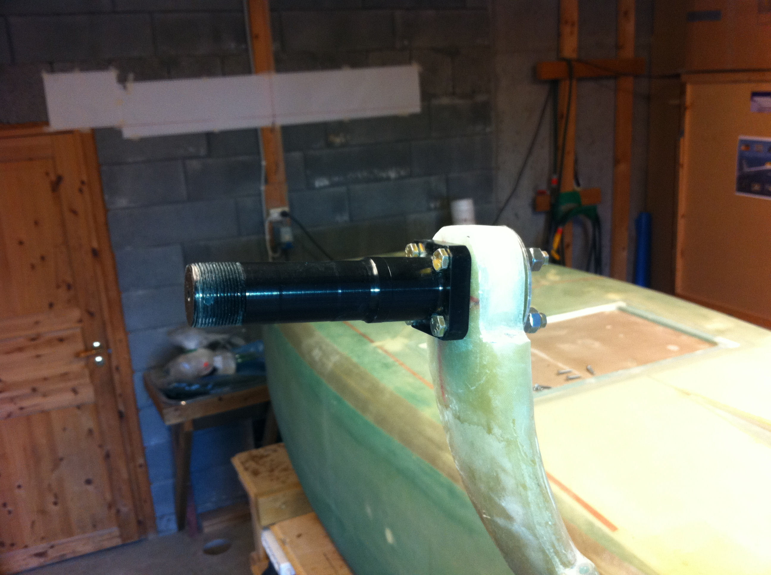
2011-07-08: The axle is mounted and I am now ready for calculating and measuring the 0.25° toe-in. Based on the distance to the wall (hence the white paper on the wall), my toe-in is 13.5 mm.

2011-07-08: I’ve also shaped the strut-ends to fit the brake. This was a big job, cutting massive glass is not so easy. I ended up using the multi-tool to do the rough cuts and my dremel with a sanding-drum to shape the last contour. I have also made the back-plate of aluminum as per plans. I chose to make it round to match the countor of the strut.
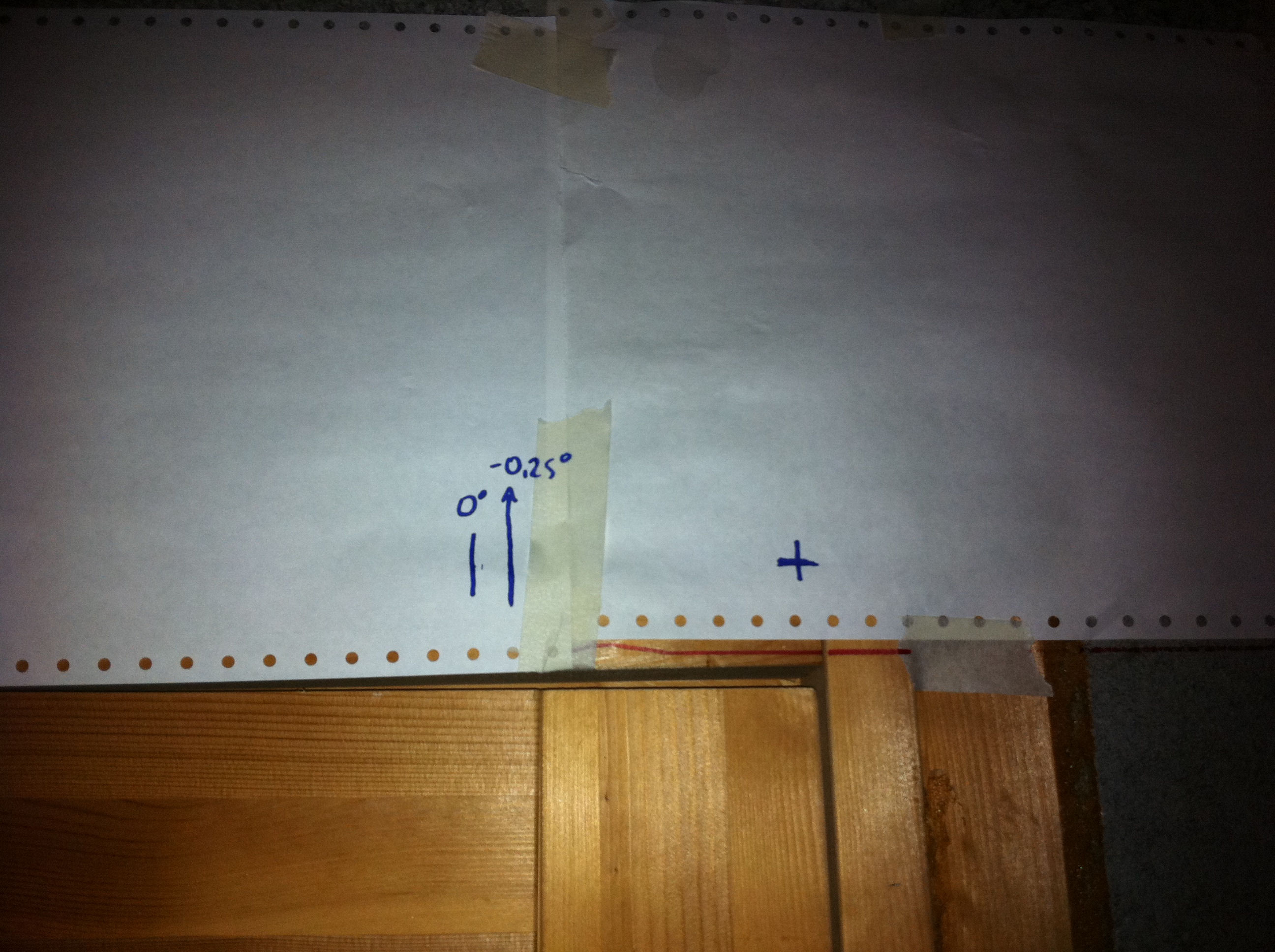
2011-07-09: I Alodined the aluminum-parts. I then measured the current toe-in based on the axle screwed on the bare strut. The cross on the paper above represents where the laser hit the wall. The zero-degree-mark is the position where the laser are parallell to the centerline. I placed my laser-leveler on the flat outer edge of the axle and holding it level it was an easy task to measure the correct toe-in. To calculate the excact toe-in I use Phytagoras formula: tan(A)=a/b. I know the angle A (89.75) and the distance b that is the distance from the laser-point to the wall. The distance a will then be the toe-in-distance I am looking for.
a=b/tan(A) = 3190 mm / tan(89.75) = 13.91mm (14mm).
After putting the mark on the paper, I prepped the base of the axle with clear packaging-tape to avoid the axle to be floxed permanently to the strut. I also put some Turtle-wax on the bolts to avoid them to be floxed to the strut. I made a flox-pad on the outside edge of the strut, under the axle. I also floxed the aluminum-backplate to the strut. Then I carefully tightened the nuts until the flox started to compress. By measuring with the laser against the -0.25-point, turning the nuts, remeasuring with the laser, turning the nuts again I finally made the laser to meet the correct toe-in-point. Now the axle is let to cure overnight.
This was a major milestone for me. I have been anxious to screw up this point. It turned out to be not so complicated as I feared. However, I used a lot of hours in this step. Almost 11 hours just to come so far…
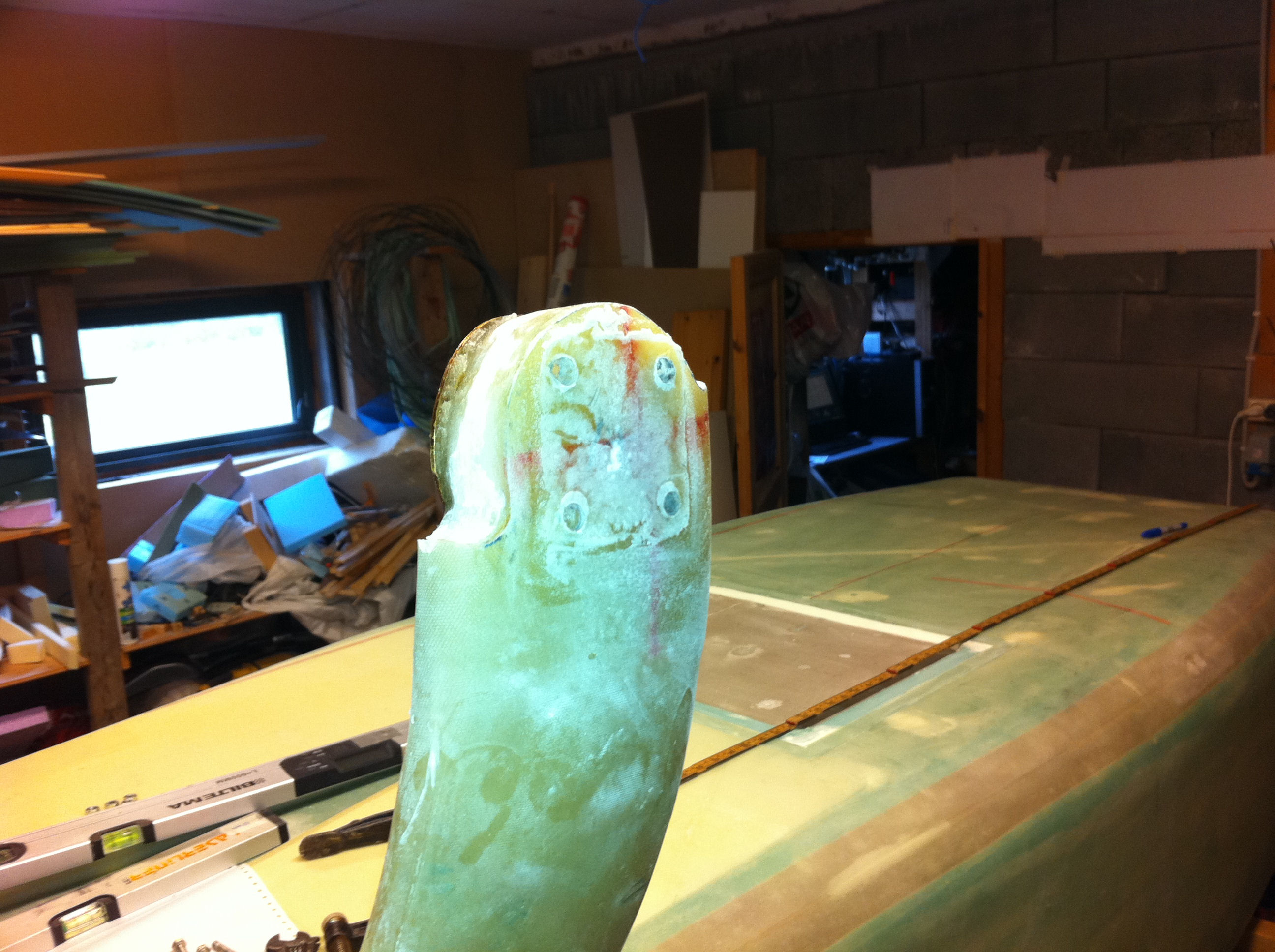
2011-07-10: After curing overnight I dismounted the axle and brushed up the flox-pad and redrilled the holes since some flox had entered the holes.
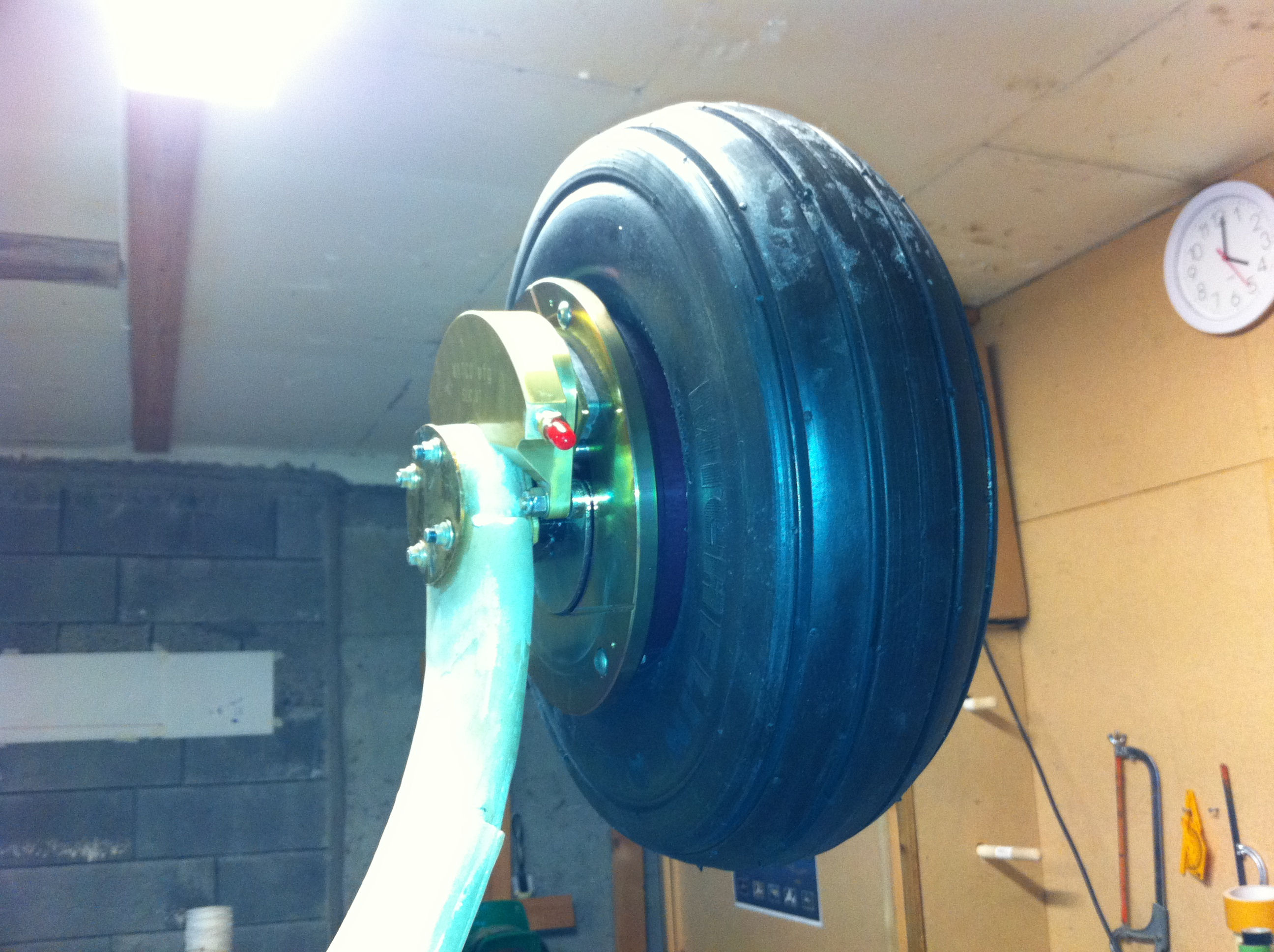
2011-07-10: The wheel is mounted for the first time.
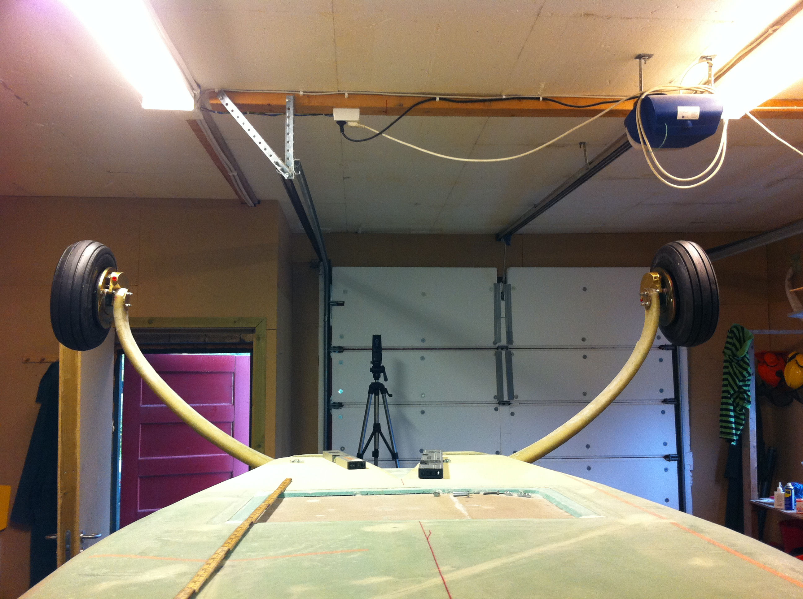
2011-07-10: Both wheels are in place – cool… 🙂

2011-07-11: Made heat-shields of 0.063″ aluminium. I followed Bernard Siu’s approach and made them to be sandwiched between the axle and the brake to avoid heat-transfer to the strut.

2011-07-11: The heat-shield is in place and angled out from the rotor-disc. It shields the strut from the radiant heat from the rotor-disc. I will also cover the strut with fiber-frax after I have built the fairings and finished the plane.
Still to do is installing the brake-lines. I ended up buying steel-braided teflon-lines all the way from the caliper to the LG bulkhead. I will not mount this until later in the process. The consequence of using these lines is that the conduit in the trailing edge of the MLG was to small as I said in step 2. I ended up cutting a slot in the conduit with the multi-tool from top to bottom, then pulling out the vinyl-tubing. This left me with a nice fiberglass-conduit big enough for my brake-lines to pass through. Later I will cover the whole thing with the fairings, so the opening will not be of any problem for me.
Landing gear box
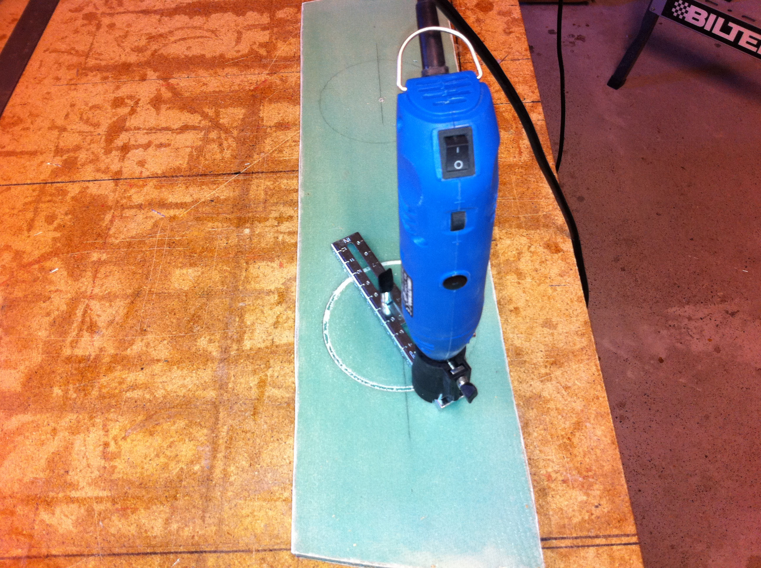
2011-08-06: The landing-gear-box is just three pieces of foam put in place ontop of the wheel-well inside the tub. I cut out the foam and glassed 2 BID on both sides. The middle-piece will have two inspection-holes in it. The size is not given, so after reading some builder-blogs I found that 4,5″ diameter would be good. I guess I will need to be able to put my hand down here sometimes. I just used my Dremel-look-a-like with a router-bit and a circle-cutter. Piece of cake to make nice round holes. Routed from both sides.
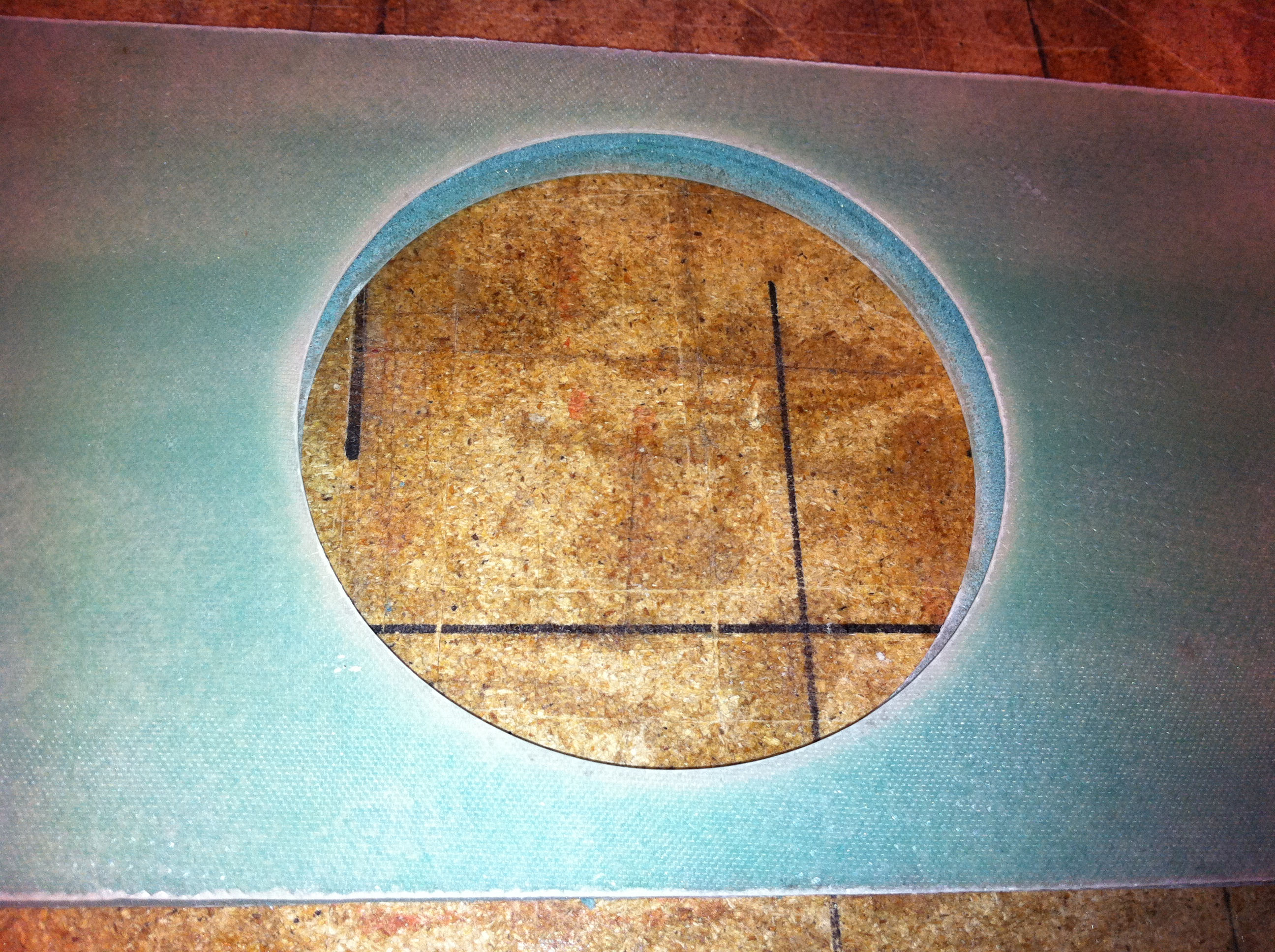
2011-08-13: The plans says nothing about what to do with the exposed foam inside the hole. I may very well over-engineer this part, but I dont like to have exposed foam so I simply routed out 1/4″ of foam and filled it with flox and glassed 2 BID inside.

2011-08-13: Glassed and peel-plied and set to cure. The result was very nice!
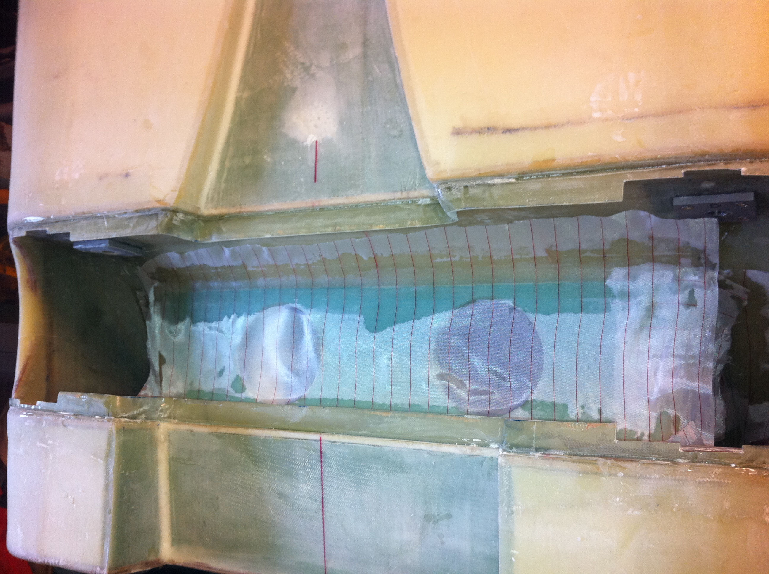
2011-08-14: The foam are floxed in place, taped with 2 BID and peel-plied. This small operation (the LG-box) takes long time because I have to flox and glass in small steps, then wait for the glass to cure before I can go on to the next step.
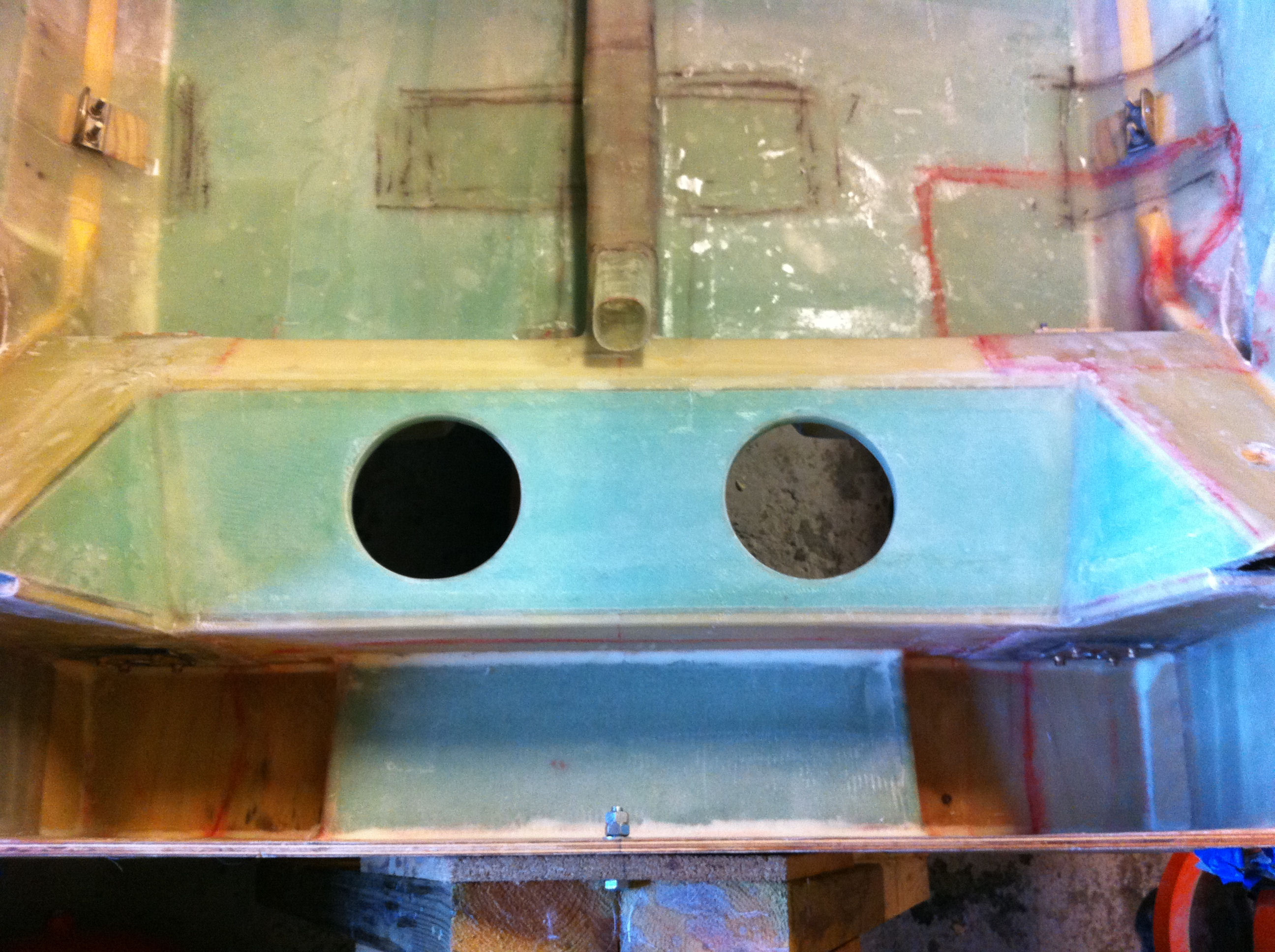
2011-08-19: Finally the LG-box is finished. Turned out to be quite nice actually.
2012-01-06: I have bought various brake-items to complete the brake-installation. I will not mount the brake-lines until further in the project to avoid the lines and tubing to be damaged. Will come back later to update this part when I have mounted the brakes.