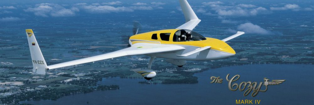
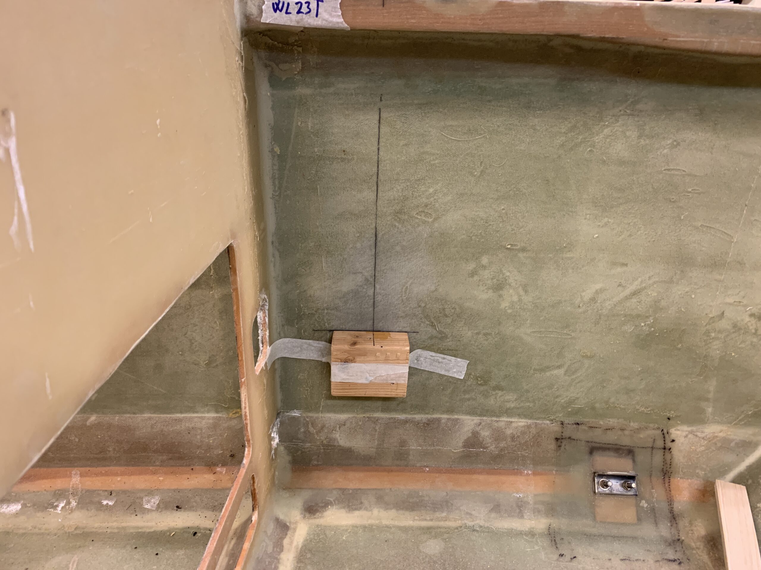
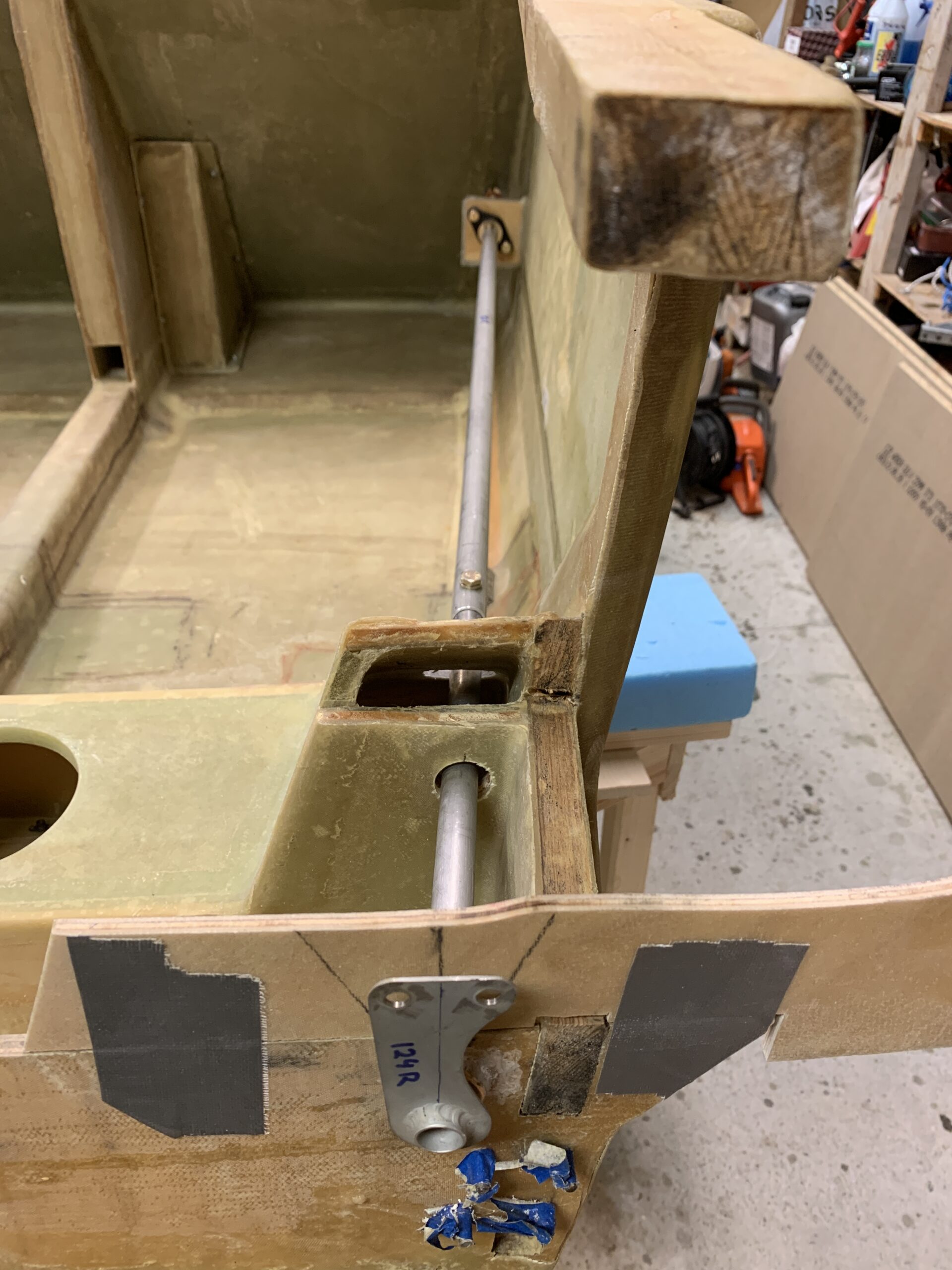
2021-02-28: Started to measure the correct waterline and fuselage station inside the tub where the bearing blocks will be floxed to the tub. Test mounted the left side control assembly and discovered that I had to adjust the pre drilled holes a bit, both through the seatback and through the landing gear bulkheads. It was an easy task using my Dremel and a sanding drum. Then I bondoed some wooden block to support the bearing blocks when floxing them to the tub.
2021-03-02: Attached the bearing blocks using the plans method.
2021-03-03: Made a flox corner between the fuselage side and the bearing blocks, and glassed the bearing blocks with 2 BID on both sides. Peel plied after as usual.
2021-03-05: Remounted all the hardware again, and floxed in the CS-123 bushings (flox on both sides).
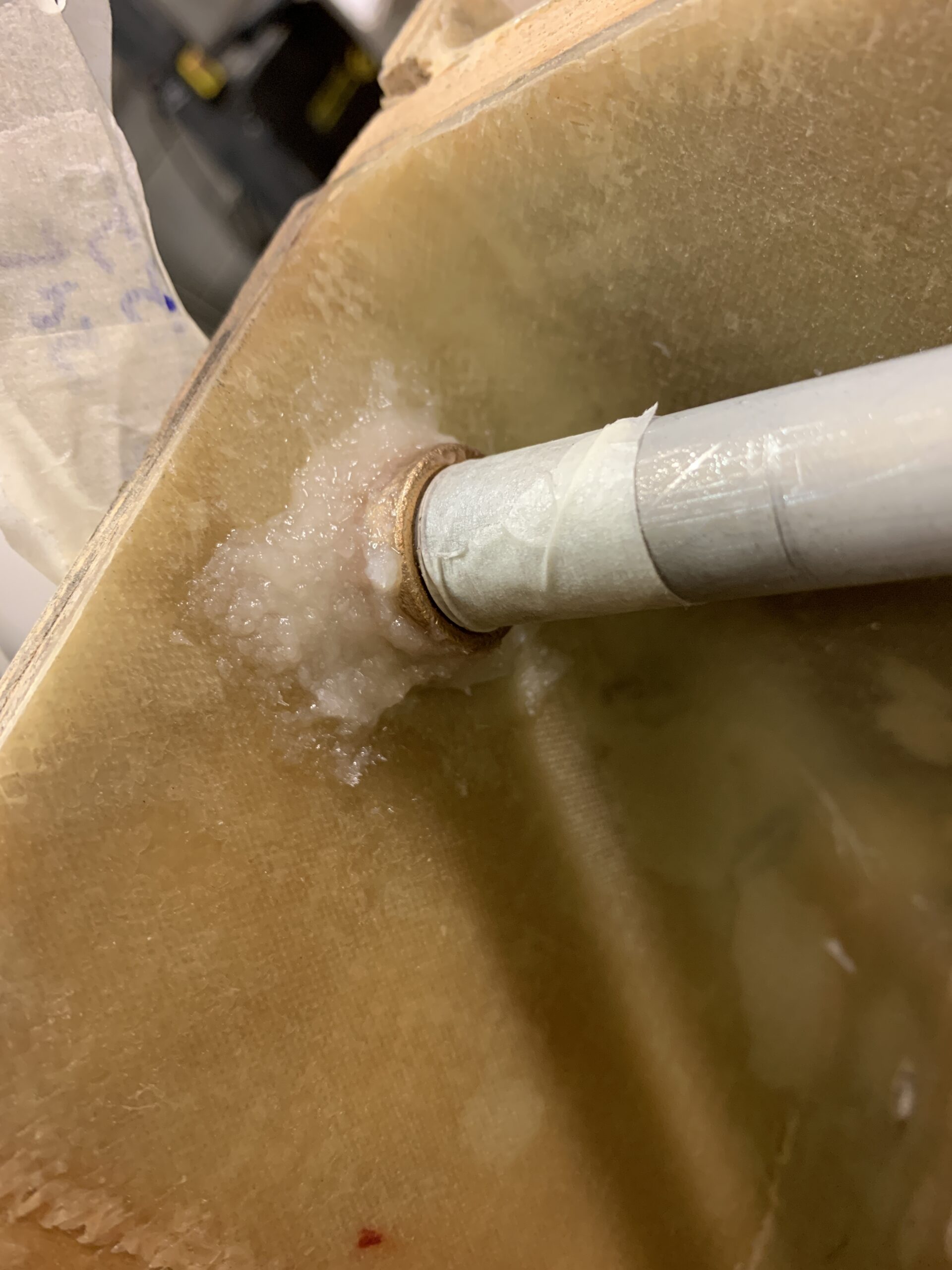
After cure I sanded the flox smooth.
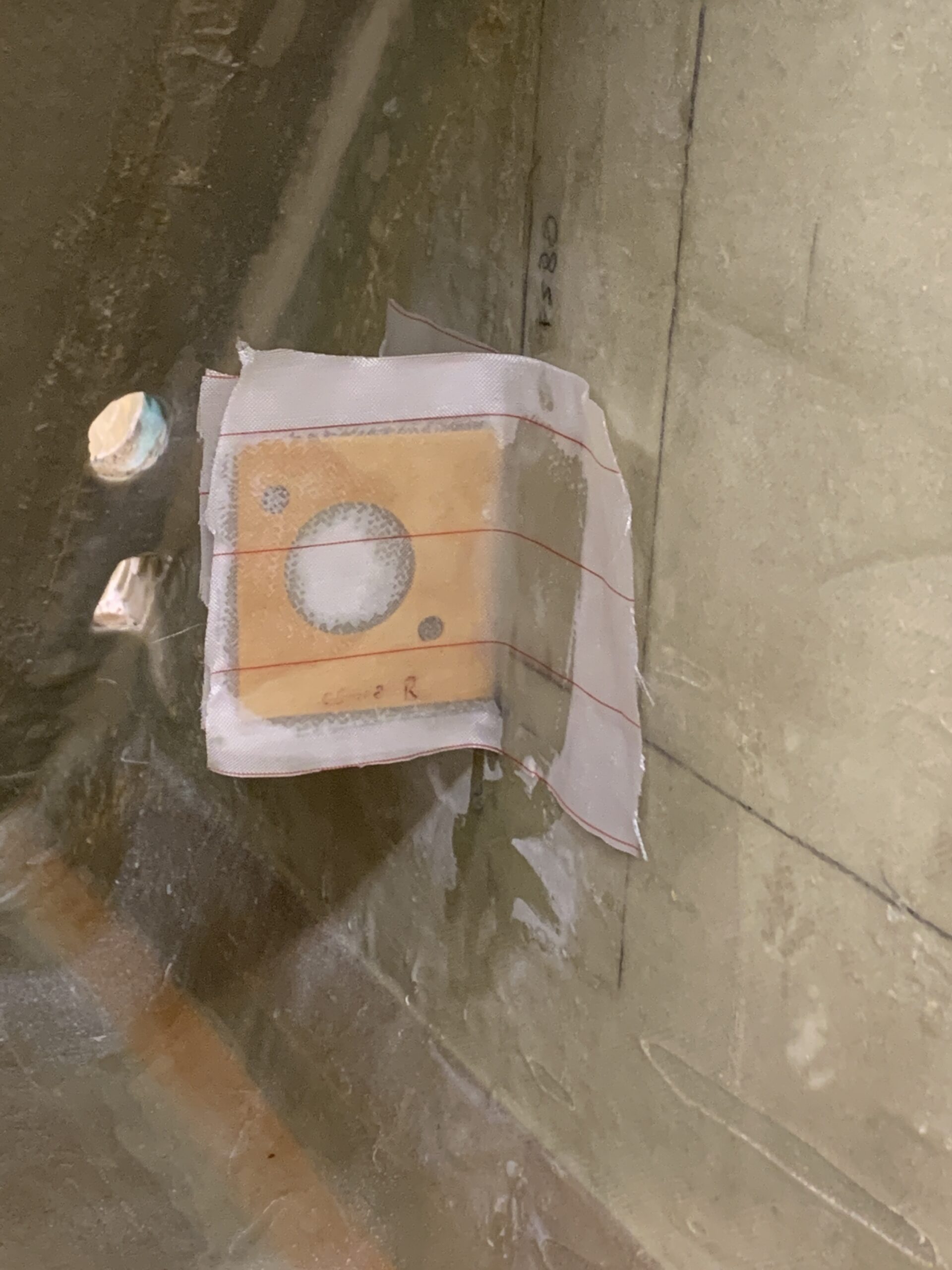
2021-03-11: Finally I could drill the holes to attach CS-121 to CS-122.
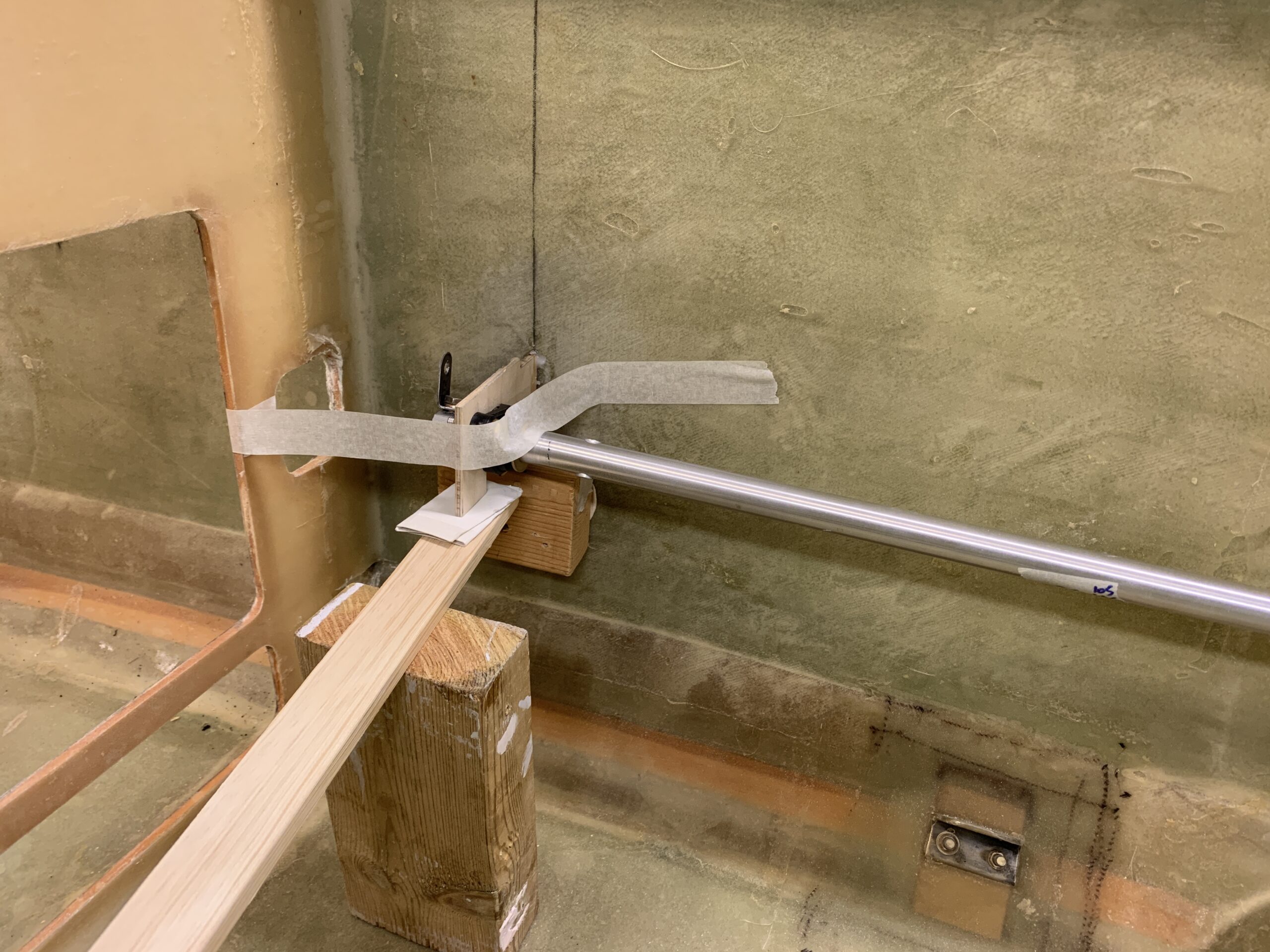
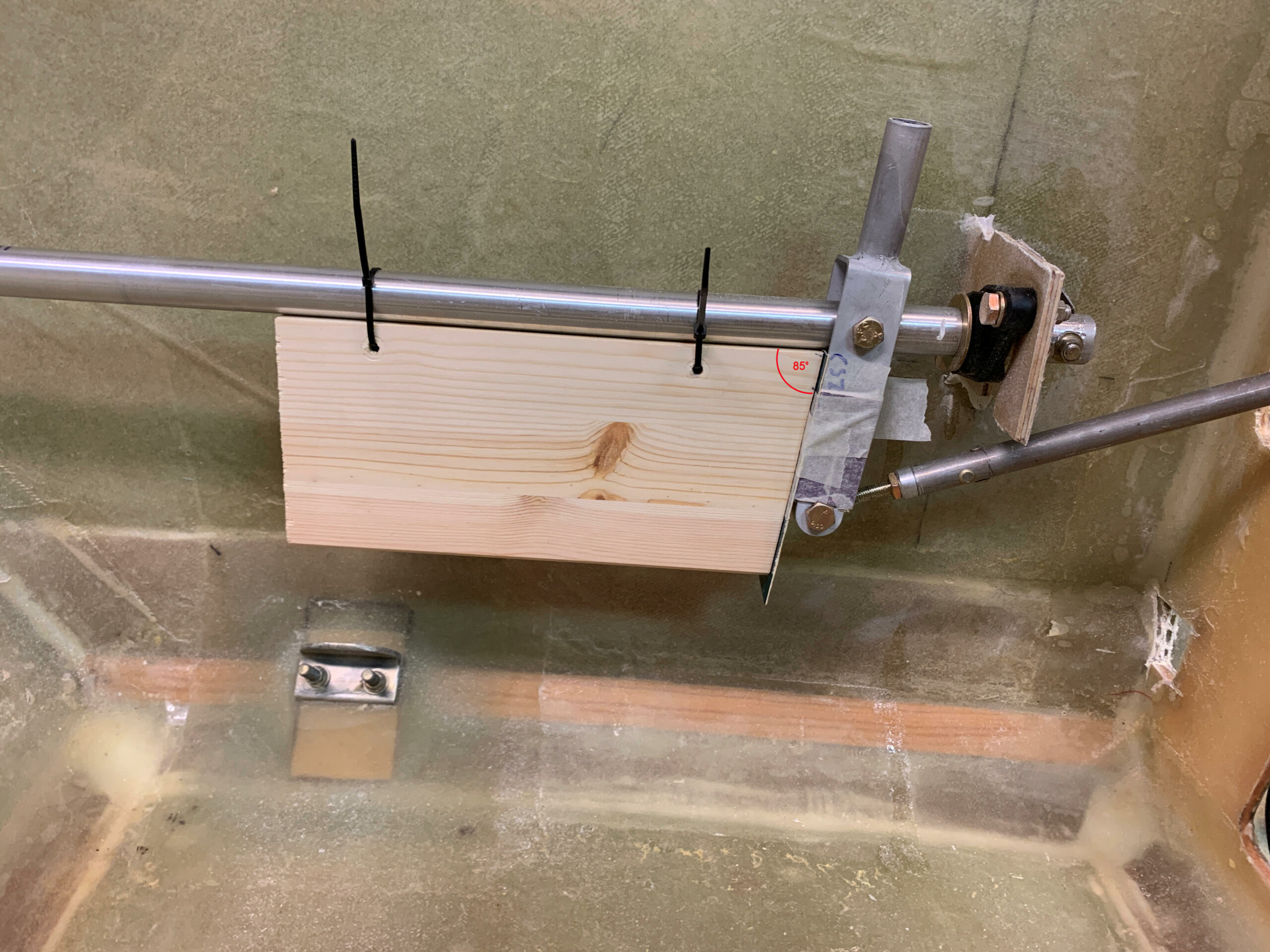
First I aligned the control tubes so that the attachement holes for the grip sticks was absolutely horizontal and fastened the tubes in that position.
Then I draw a vertical line on the control horn, and on the firewall I mounted a temorary piece of plywood and draw two lines 20 degrees in each direction.
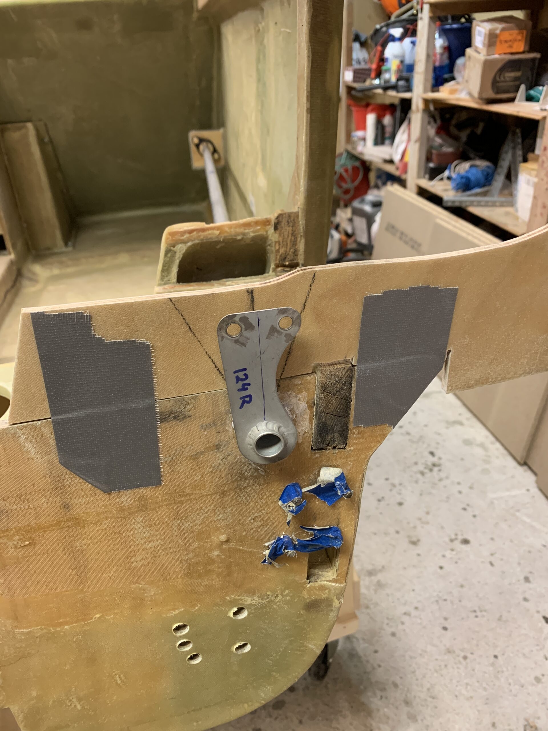
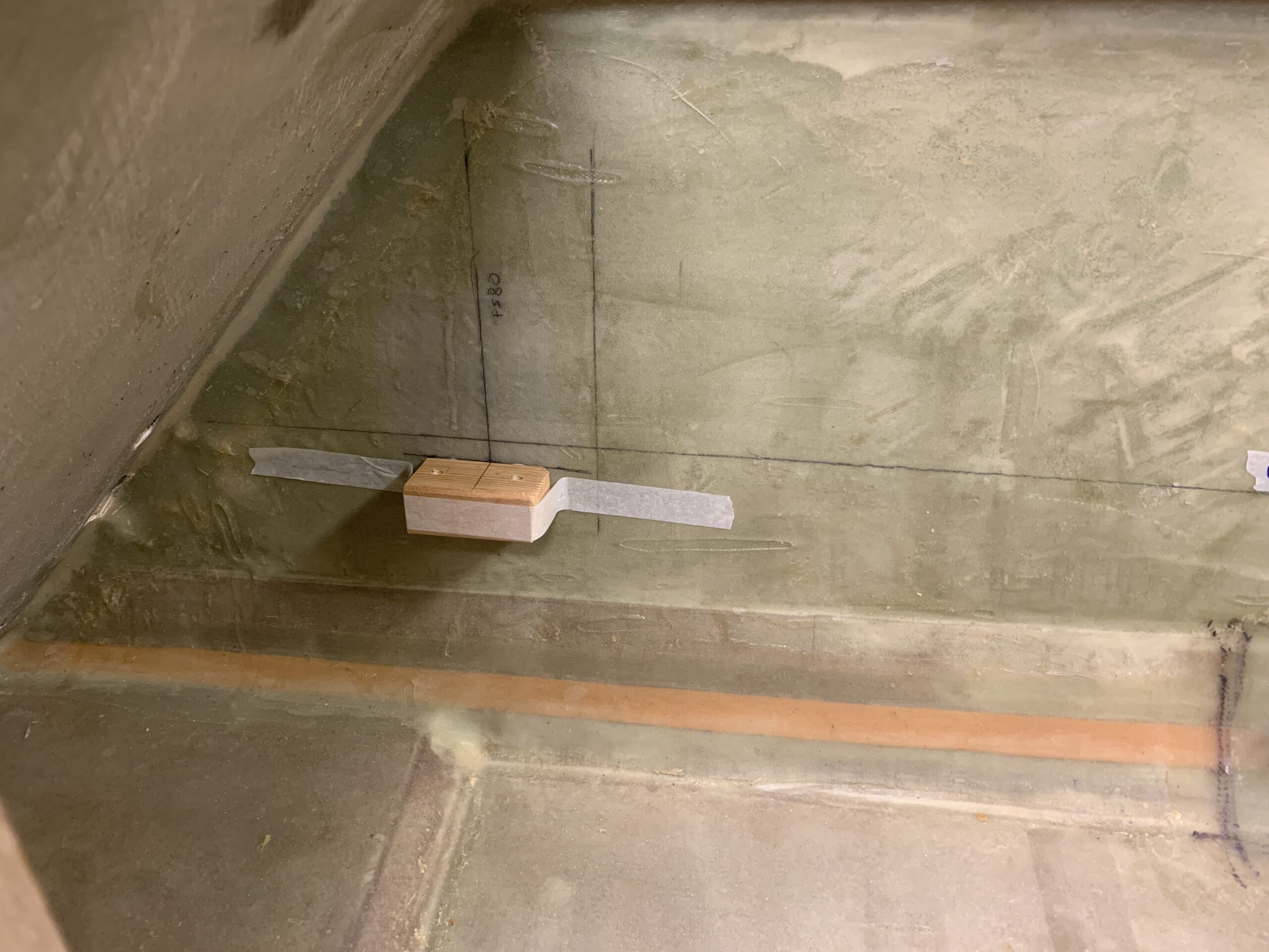
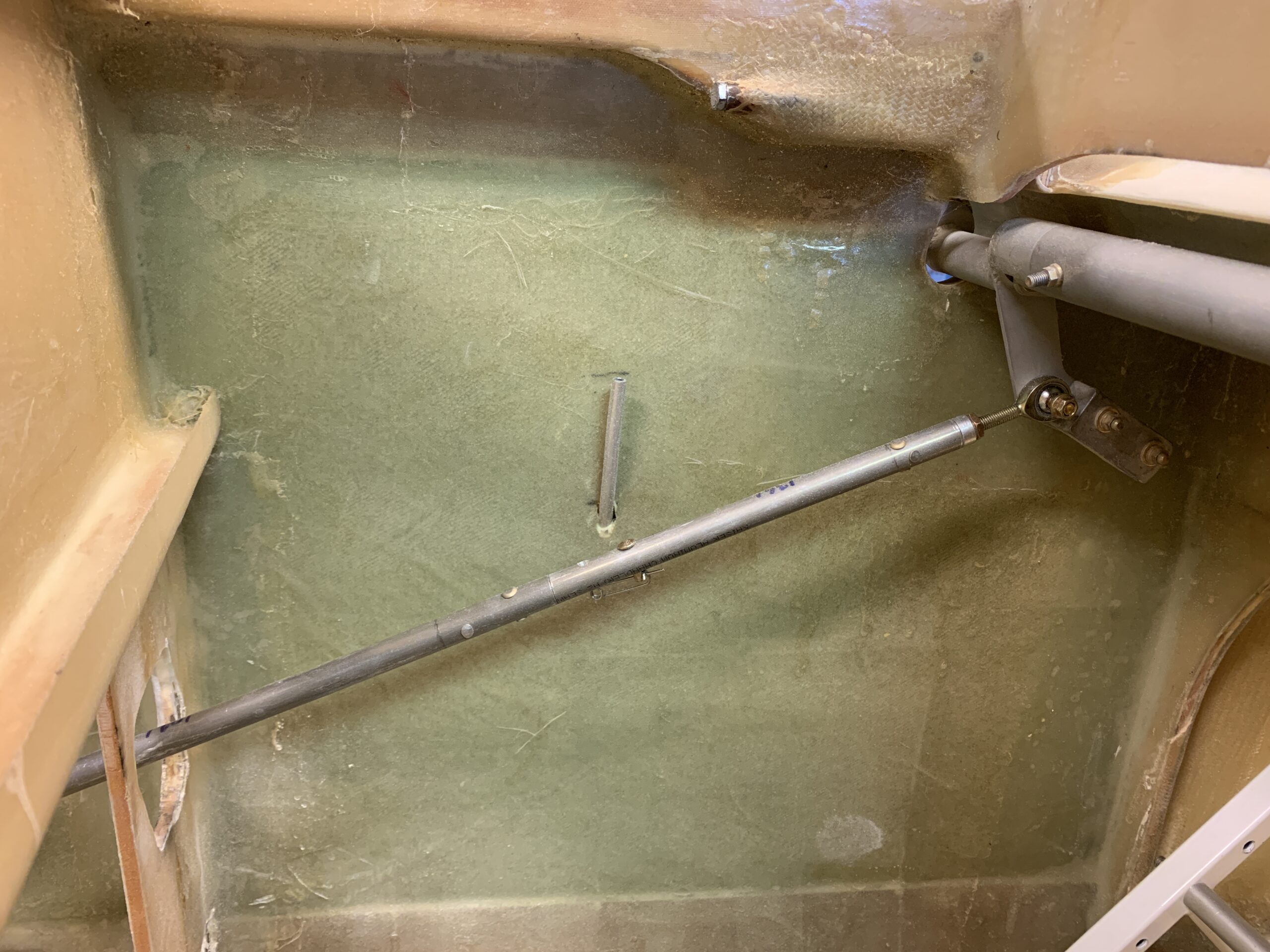
I mounted the horizontal steel rod between thw left and right CS-124 with all the rodends and bolts to get the minimum required distance between the firewall and the hardware with the control horn deflected 20 degrees. Then I marked a reference line on the CS-122 tube just in front of the CS-123 bushing.
Now I measured how long CS-122 protruded into CS-121. I ended up cutting away 4 inches so that CS-121 ended up beeing 34″ long. That gave me an overlap of 1,5 inch approx. I then drilled a pilot hole on each side through CS-121 and CS-122. Dismounted the tubes and drilled up to 1/4 inch in steps. Again – it’s important to disamble CS-122 from CS-121 to avoid them to stick to each other permanently due to the aluminum from CS-121 almost welds itself into the CS-122.
Finally I could mount it all together again.
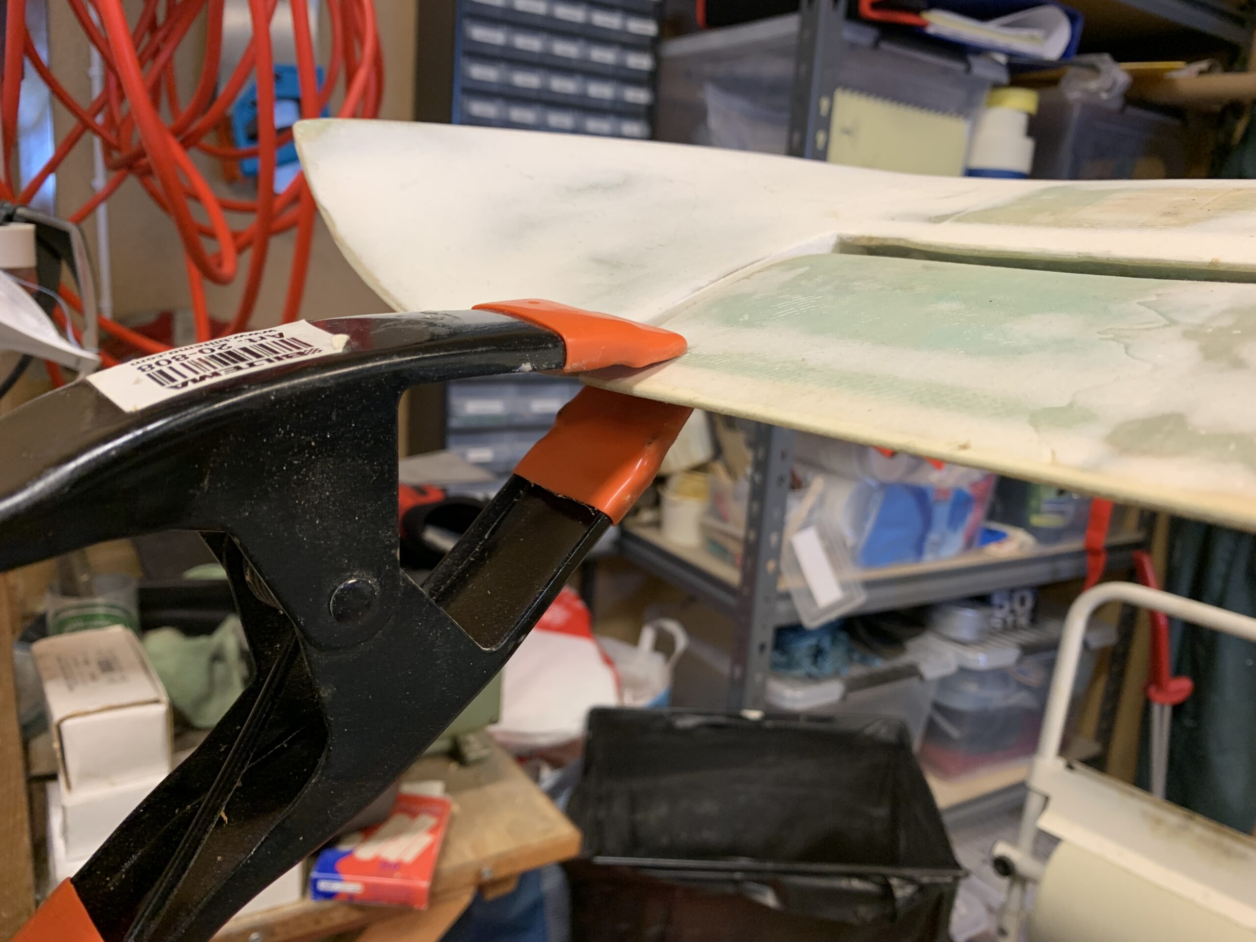
2021-03-20: I assembled the control tubes for the elevator on both sides. Then I did some head scratching to find out how I could manage to place the control stick with a 5 degrees forward cant. After some attempts using cardboard templates I ended up making a template of some wood, cutting it with a 5 degree angle, and mounted it to the control tube just behind the stick.
Since the CSZA-stick is tapered towards the bottom, I made it rectangular by using some cardboard. Then I could align the stick with the wood and then get a 5 degree cant as the plans told me. Beforehand I had measured that the control tube facing aft was in level.
Next step was to adjust the controls by attaching the canard and mount the tubes. For the quick disconnect I did as the plans suggested by adding another clevis pin. Actually the plans told me to use a cotter pin as a redundant solution, however I found that another clevis pin was even better. In this picture I have just mounted one of the pins.
I fastened the elevator at zero degrees to adjust the controls.
The I discovered that the hole in the instrument panel was to narrow when I deflected the stick to the right (on left side here – the same goes for the opposite side). I had to enlarge the hole quite a bit to get full movement.
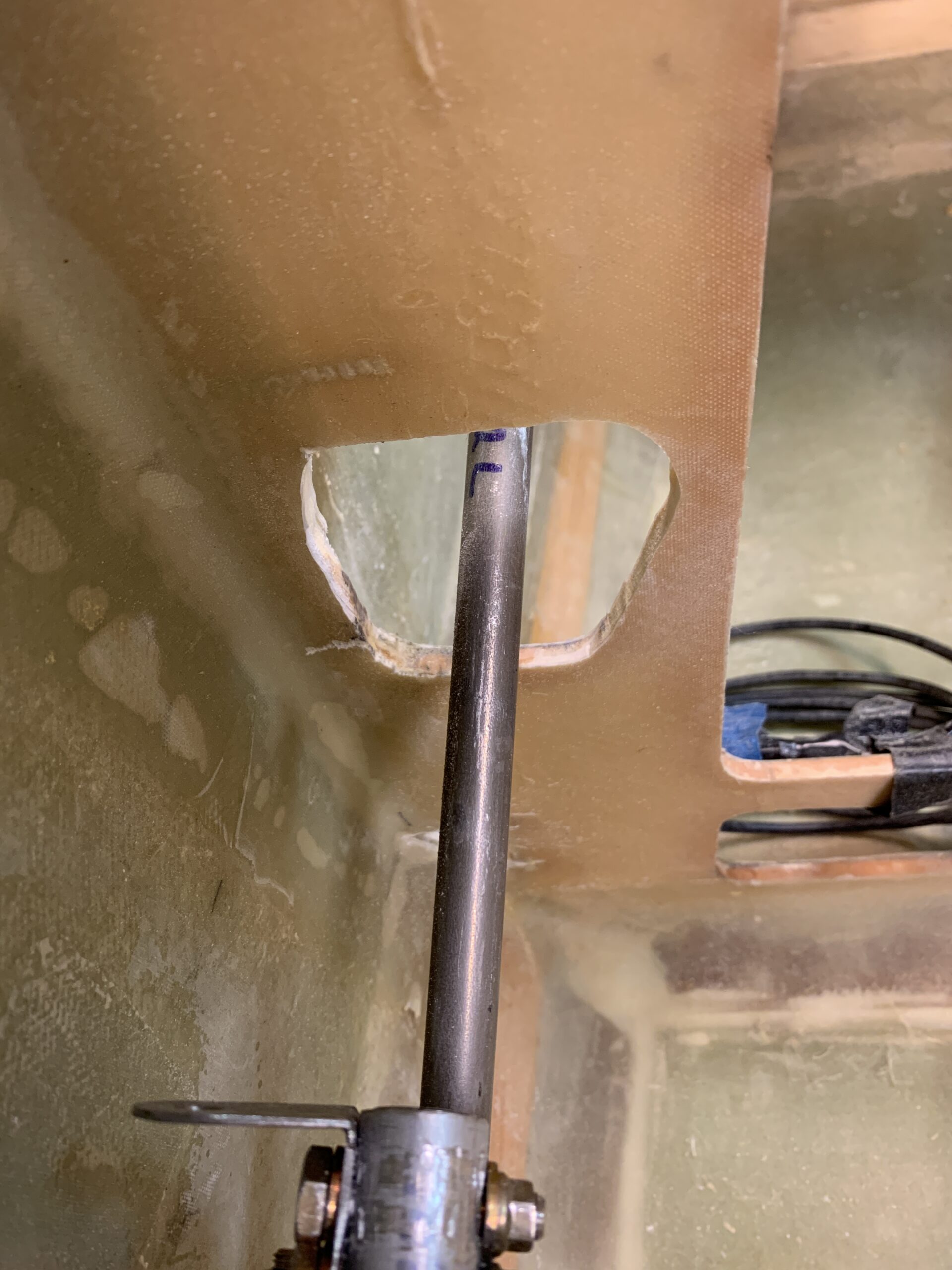
I read that other builders experienced the same thing.

Eventually I got full movement in all directions.