Next step is to contour the bottom and the sides. First I will shape the bottom corners and glass the bottom. Then I will turn the fuselage and contour the top longerons and glass both sides.
The plans are rather weak in telling how the end-result of the next steps will be, so I read through all the builder-logs I found and collected pictures and descriptions of how other did it. Then I started…
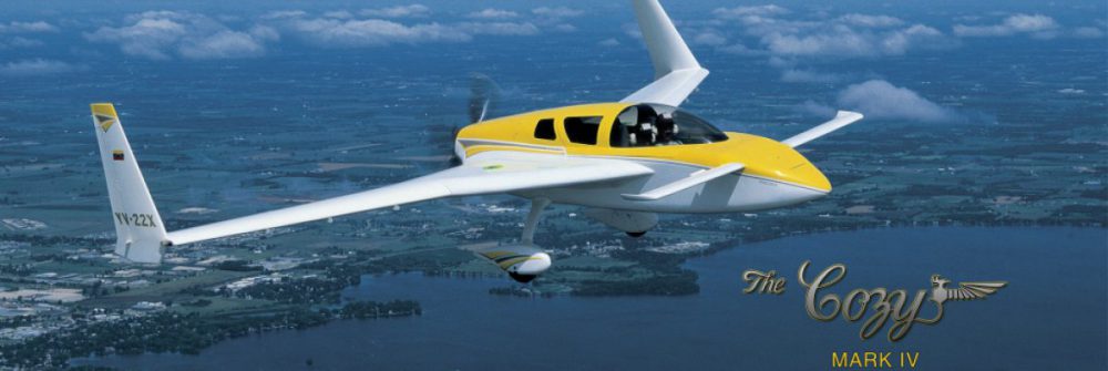
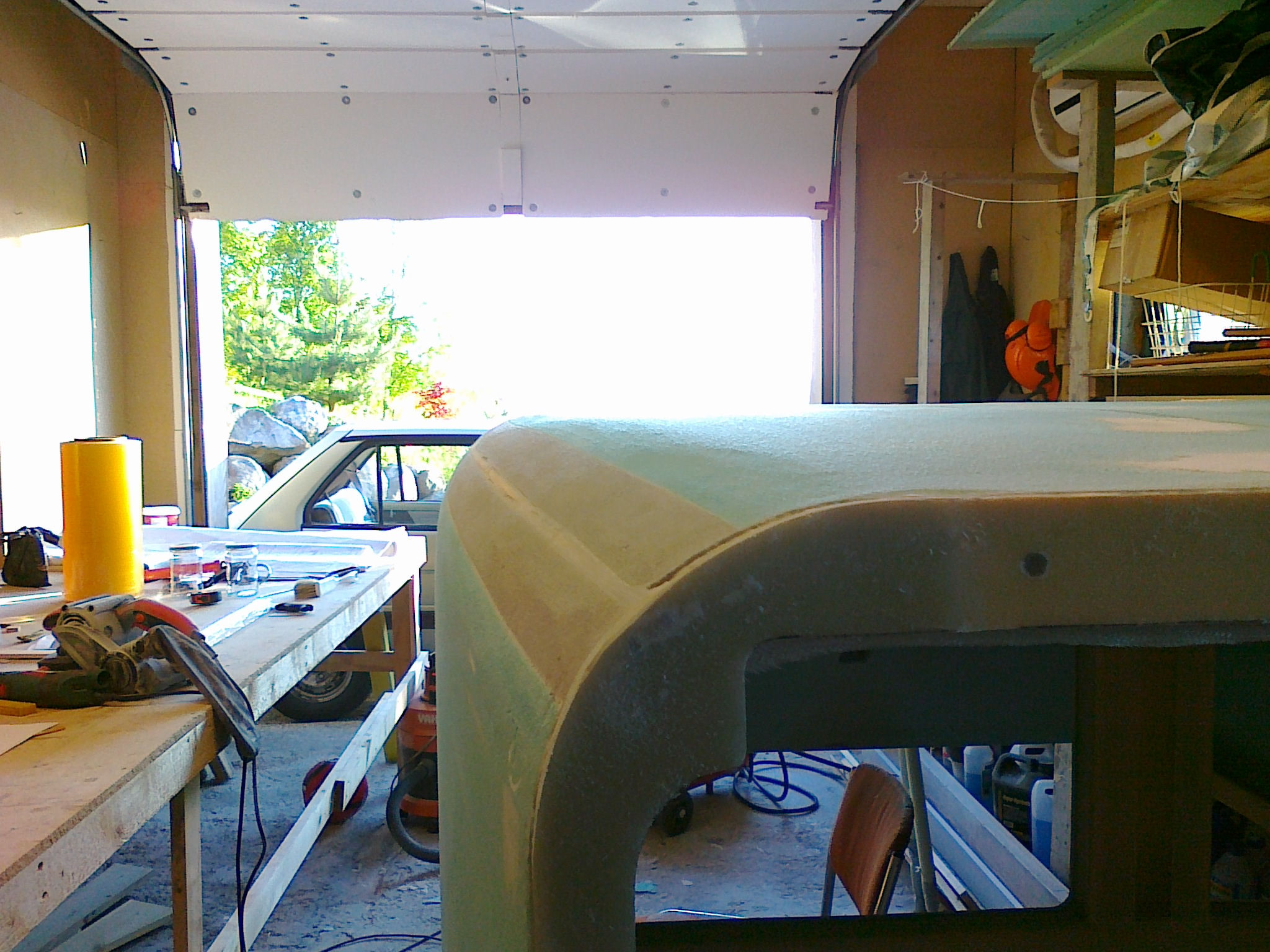
The first corner-cut is according to the plans a 45° cut into the lower longeron exposing 1/4″ inch of it. I drew a couple of help-lines on the bottom-foam and the side-foam and used my saber-saw instead of the jigsaw recommended in the plans. I also deliberately avoided to cut into the longeron. I will instead use my belt-sander to trim of the final millimeters. Using the saber-saw was a walk in the park. I’ve seen numerous blogs where the builders invents special-tools, jigs and whatever to do both these cuts and making router-jigs to shape the NACA-scoop using several HOURS on a task that just takes some minutes to do on freehand. These corner-cuts are not rocket-science. The main thing is to get both sides as symmetrical and esthetic pleasant as possible.
Bonus: Had to buy a new power-tool: The belt-sander. Didn’t have this in my collection!
Bonus2: Since I used Divinycell instead of the plans Last-a-Foam as spacer-material (the grey foam in the picture), cutting, sanding and shaping the countors was easy since both materials have the same density and properties.
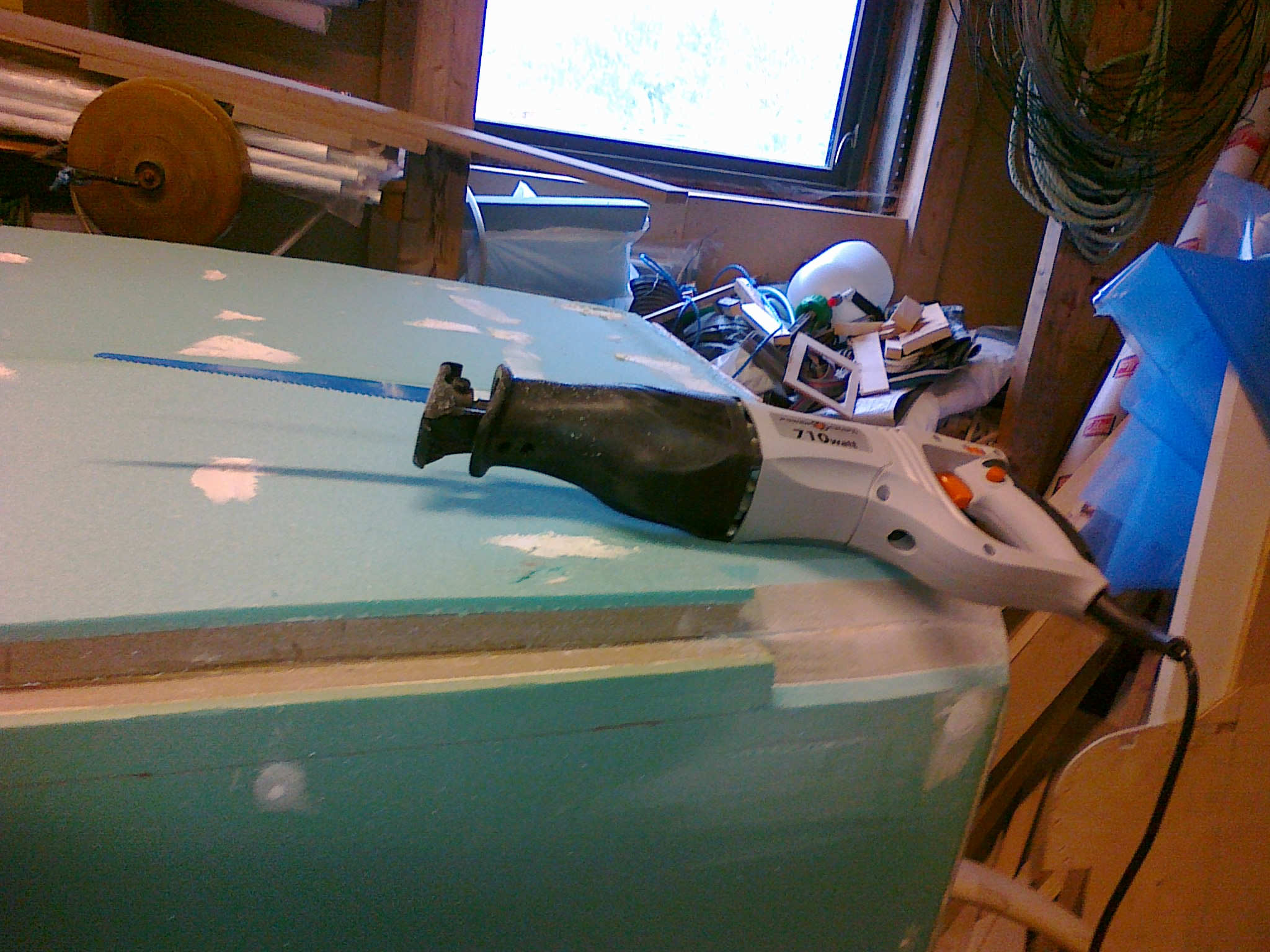
The rest of the cutting was done by hand with a hacksaw. An easy task which took only a couple of minutes. Then I used the beltsander and a sanding-board to do the last touch-up.
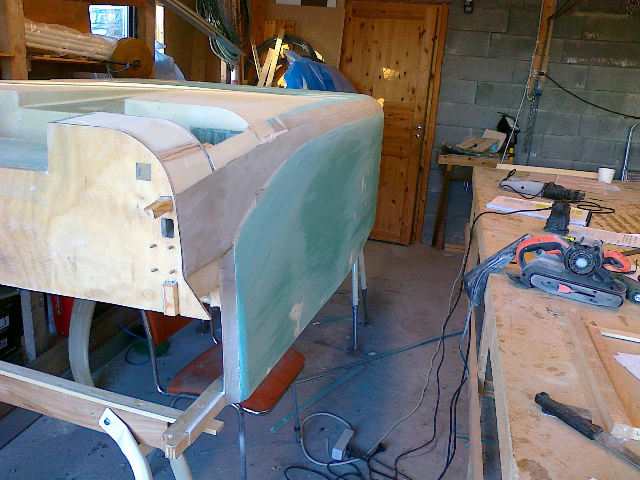
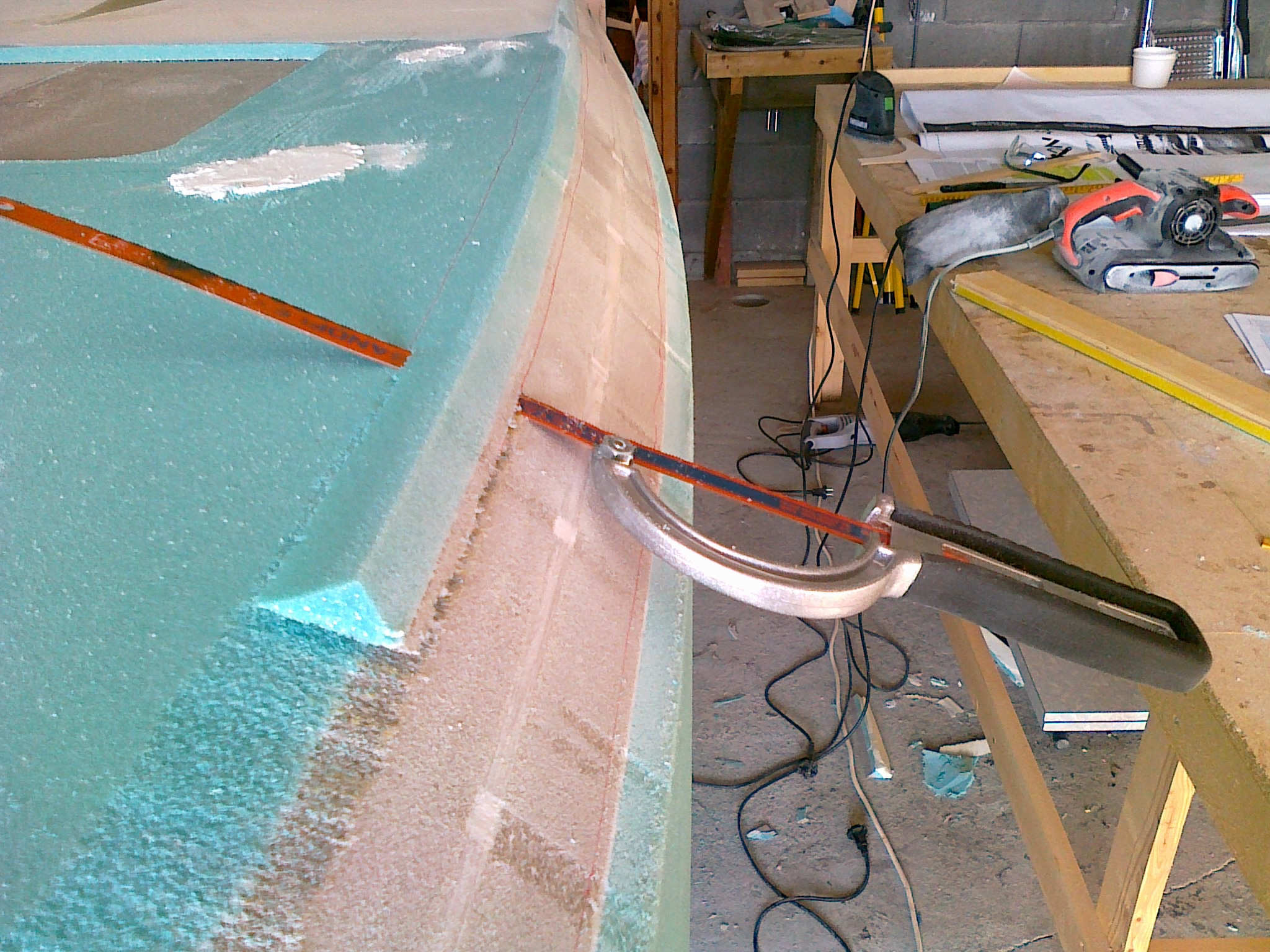
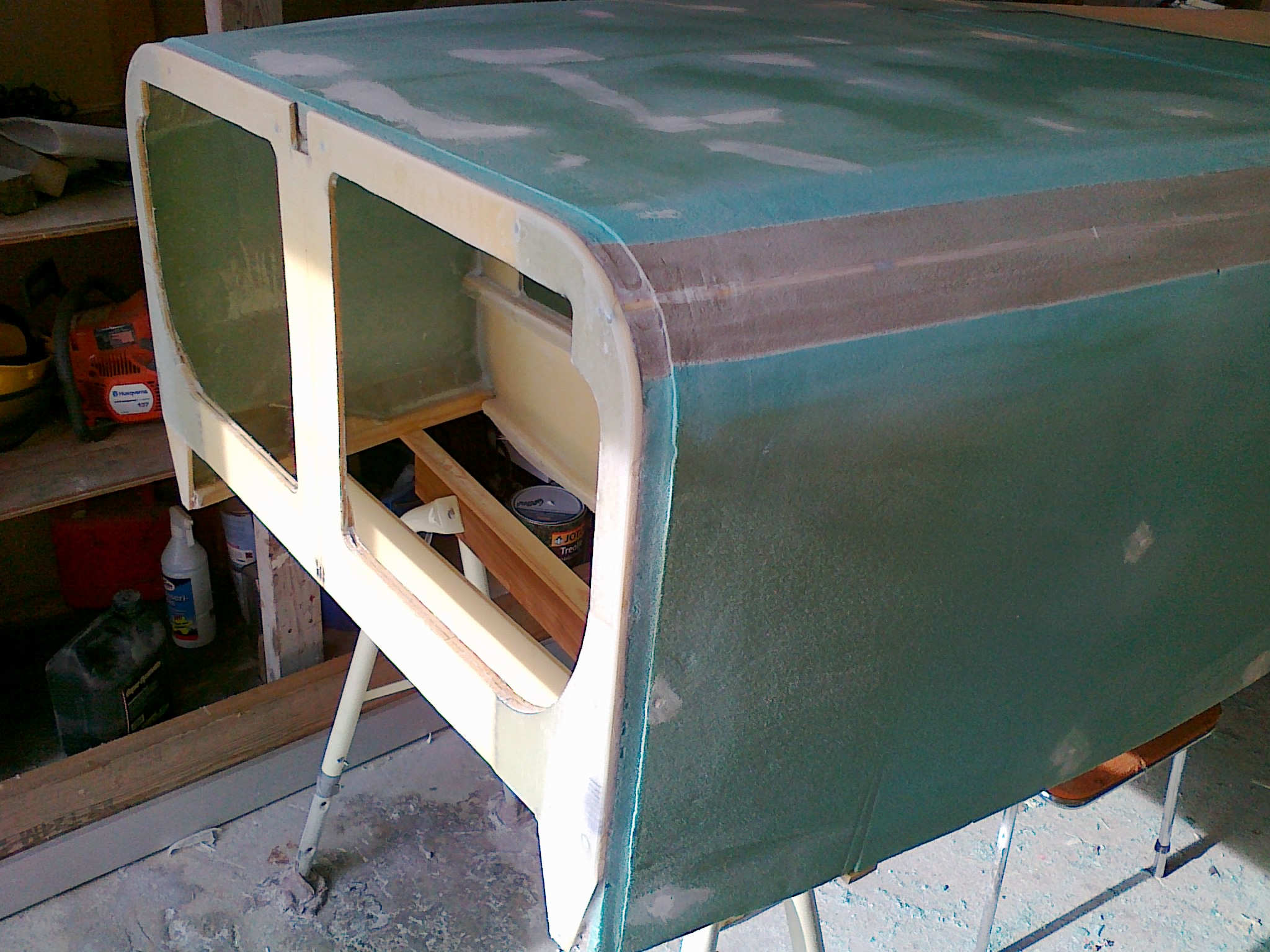
Finished contouring the left lower side.
A nice round shape. Hand-sanded the last bit to get a good round shape. Use the hand to feel if there are any bumps. Much easier to feel than to see!

Around the landing brake I should sand down 1″ / 2″ wide and 1/16″ deep area. I chose to use my router instead.
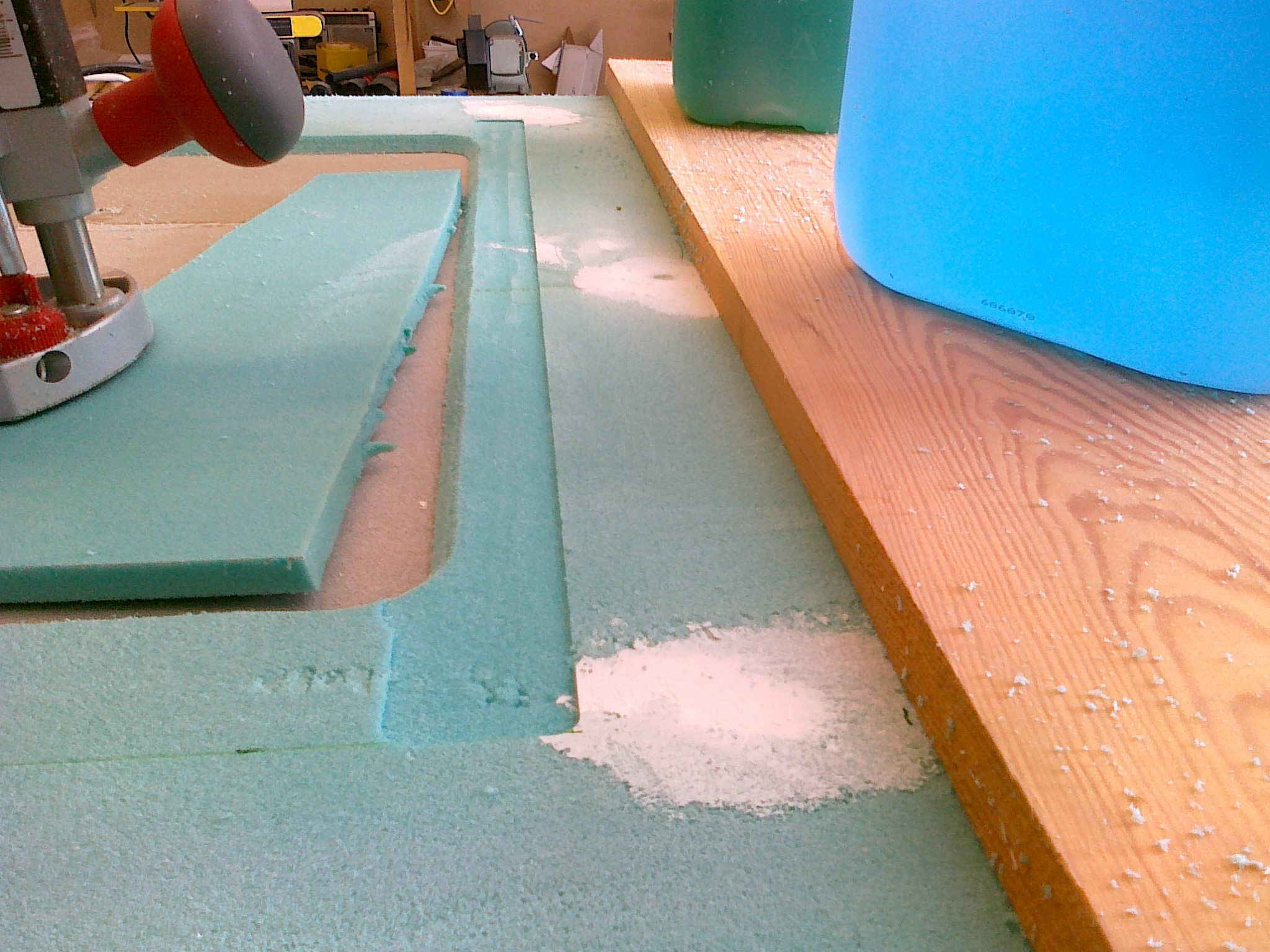
I used the same method around F22.

On the sides and aft of the landing brake (which is temporary glued in place) I built up a 1/16″ high and 1″ wide strip of duct-tape. Took 6 plies to get it flush with the landing-brake. The reason for doing this is beeing explained in chapter 9 (at least that’s what the plans tell me)…
Hindsight: In chapter 9 I didn’t manage to “pop loose” the landing-brake, instead it broke loose destroying the brake. Maybe it’s a better way to do this step?
Antennas
I have read a lot about antennas and landed on the simple solution that has been used by many builders. I tried to contact RST Engineering as recommended by many, but they refused to ship the parts outside US (!). I ended up buying the stuff I needed from Aircraft Spruce (copper-tape and ferrite-torroids) and coax-cable locally.
The info needed is on Marc Zeitlin’s Cozy-website. I also gathered very useful information from Charles Furnweger’s website.
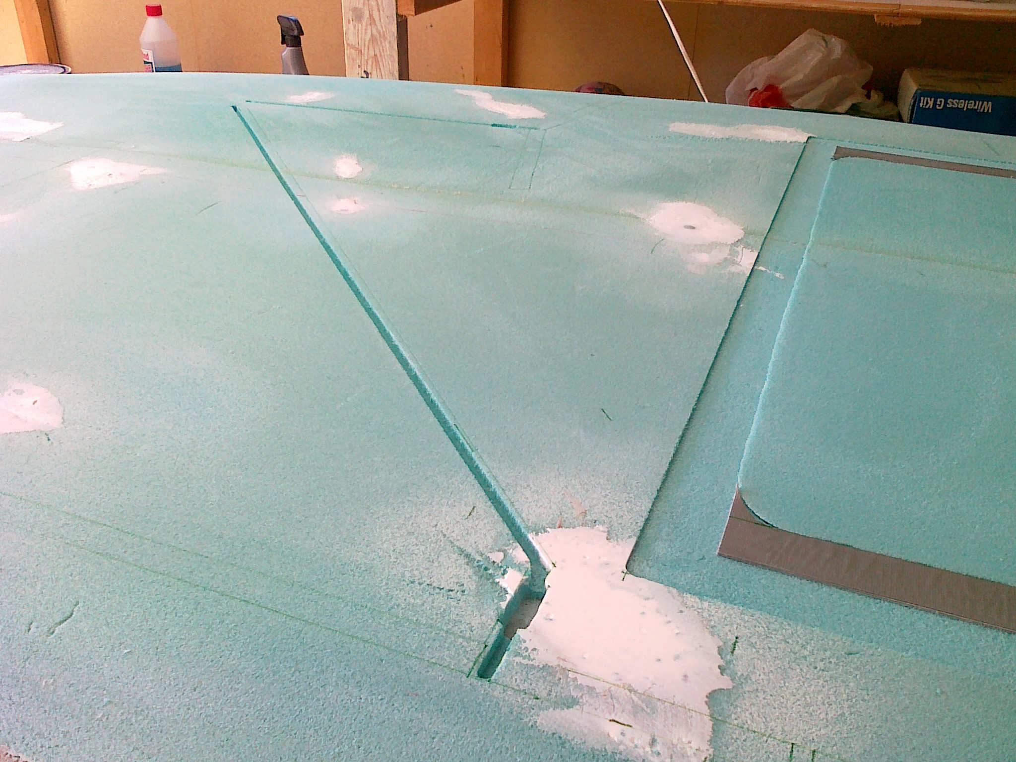
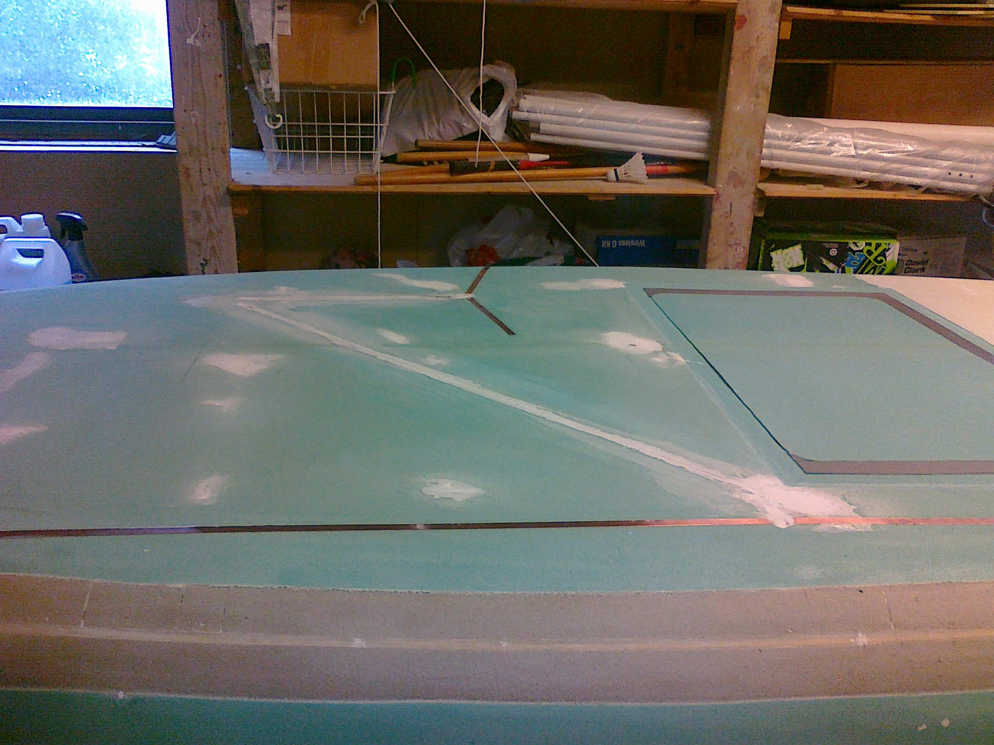
I decided to add antennas for marker-beacon and glide-slope at the bottom of the fuselage. After measuring I used my router with a 5mm bit to route the channel for the coax-cable. I also routed space for the torroids.
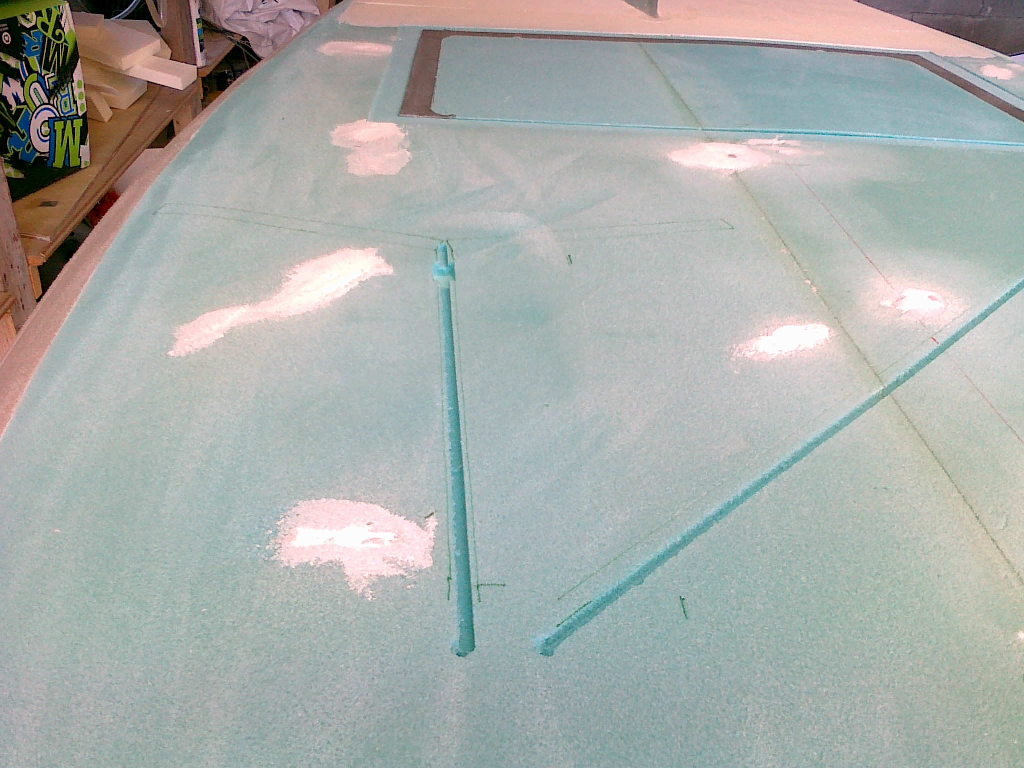
The coax-cable ends up just ahead of the instrument-panel. Remeber to make a transition between the hole and the cable-channel so the cable exits with a gentle radius. I drilled the hole pointing slightly forward as well.

I routed space for the torroids. I had to carve out some more foam where the copper-tape meets the coax to get the soldered ends to be hidden inside the foam. I later filled the channel with wet micro to secure the cable and stuff.
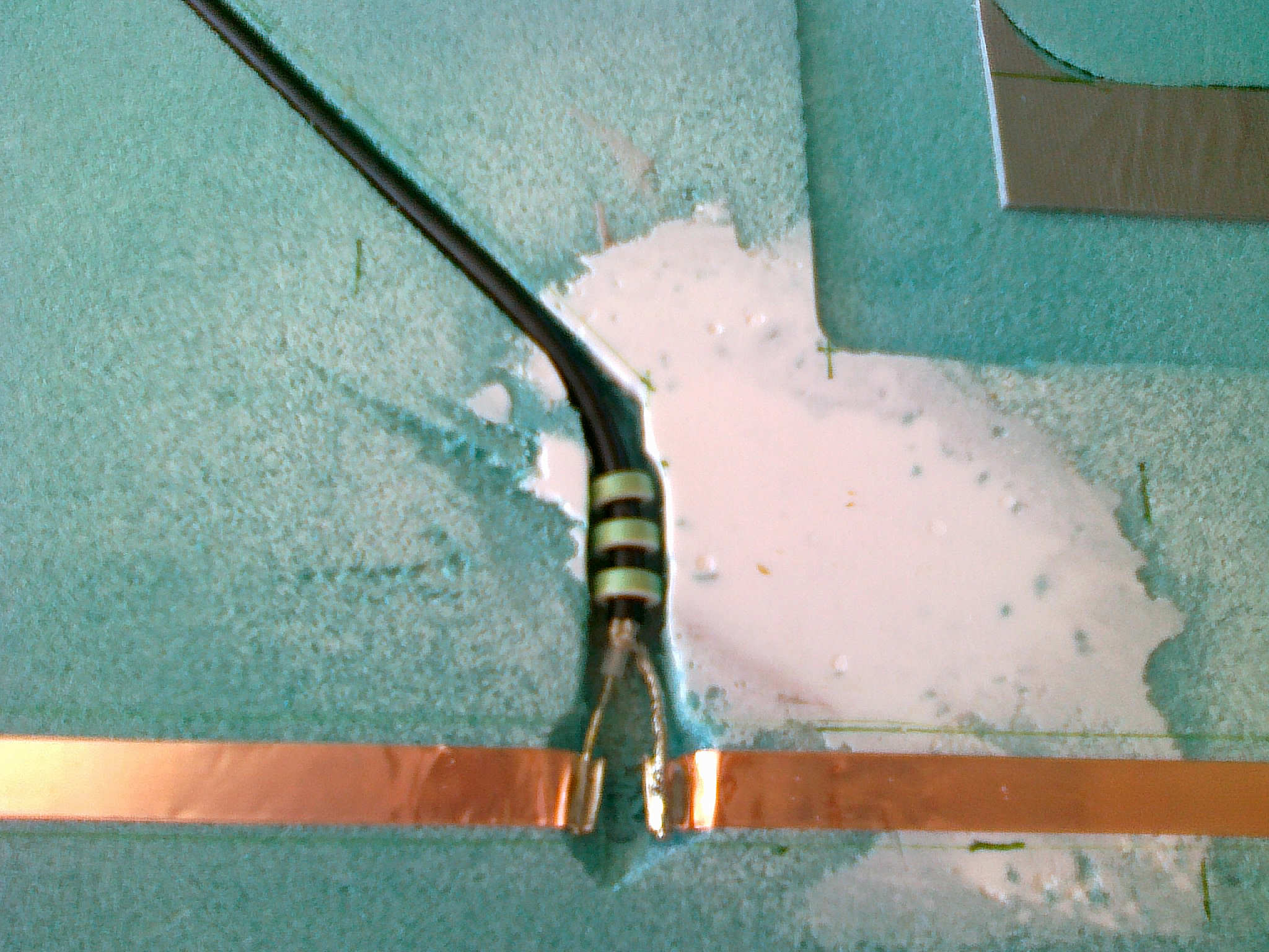
The soldering was easy, altough I had to remake the glide-slope antenna once since the copper-tape broke when I bent the wire too much. It’s delicate stuff. There are no need for recessing the copper-tape into the foam as it’s very thin.
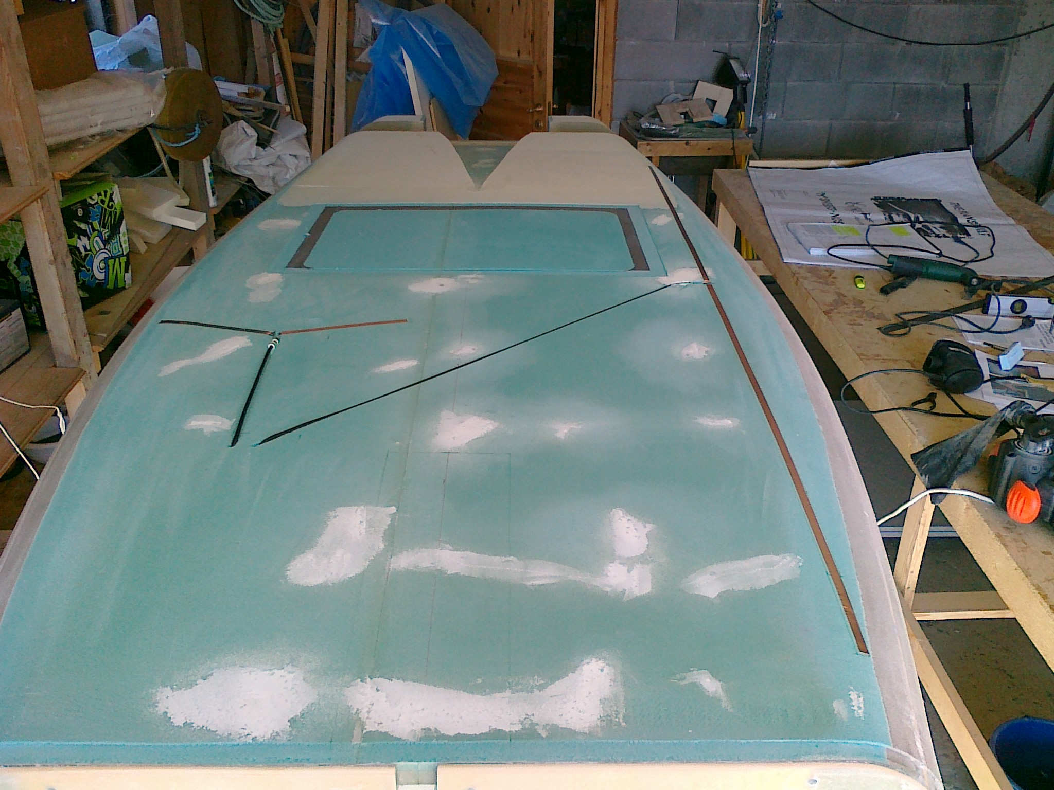
Finally – the antennas are in place. The next step is to fill the channel and depressions I made with some wet micro to ensure that the coax, torroids and soldered ends will stay in place and be protected. I also remembered to measure where the cut-outs for the wheel will be so that the routing of the cable avoids this.