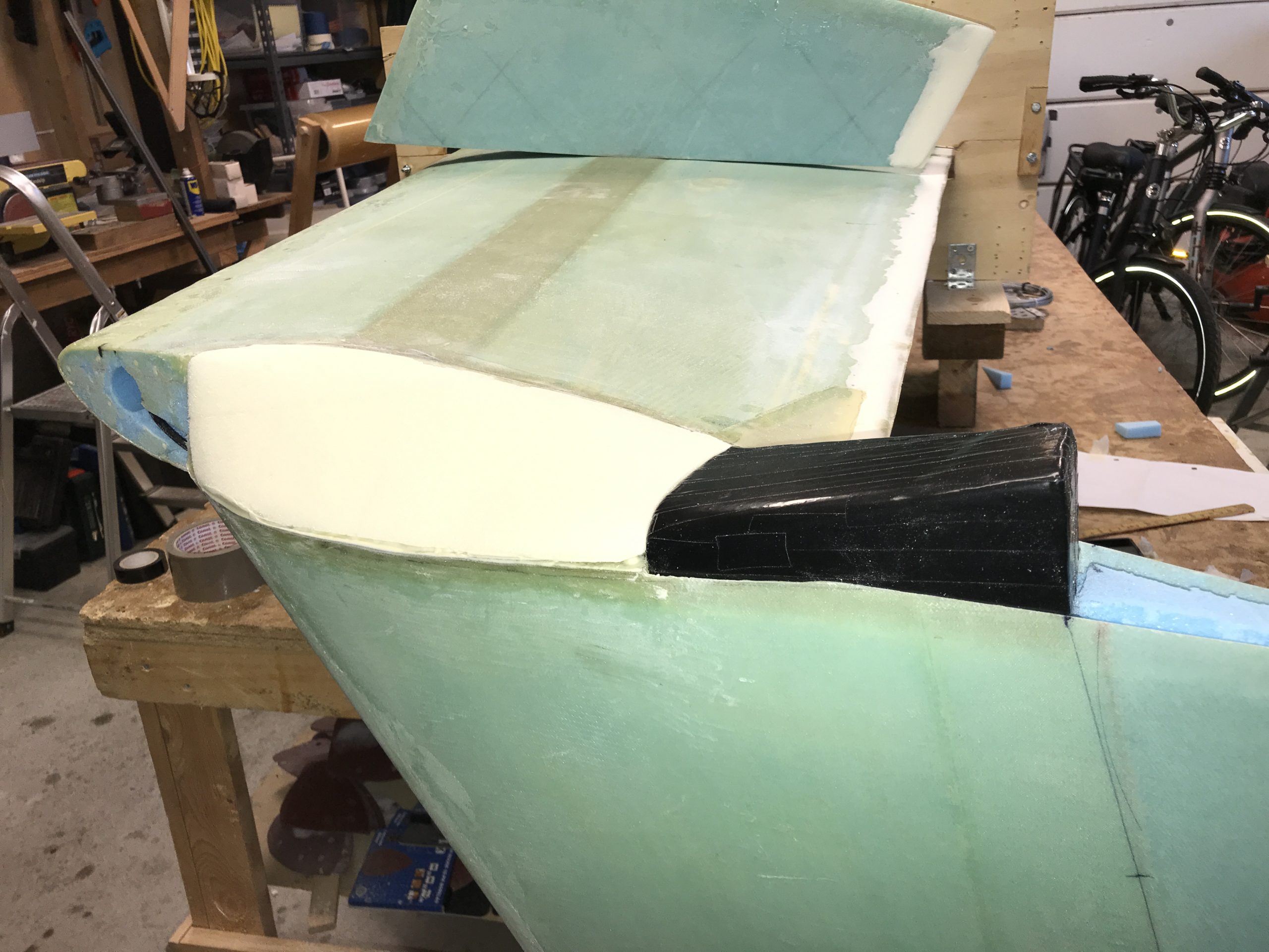
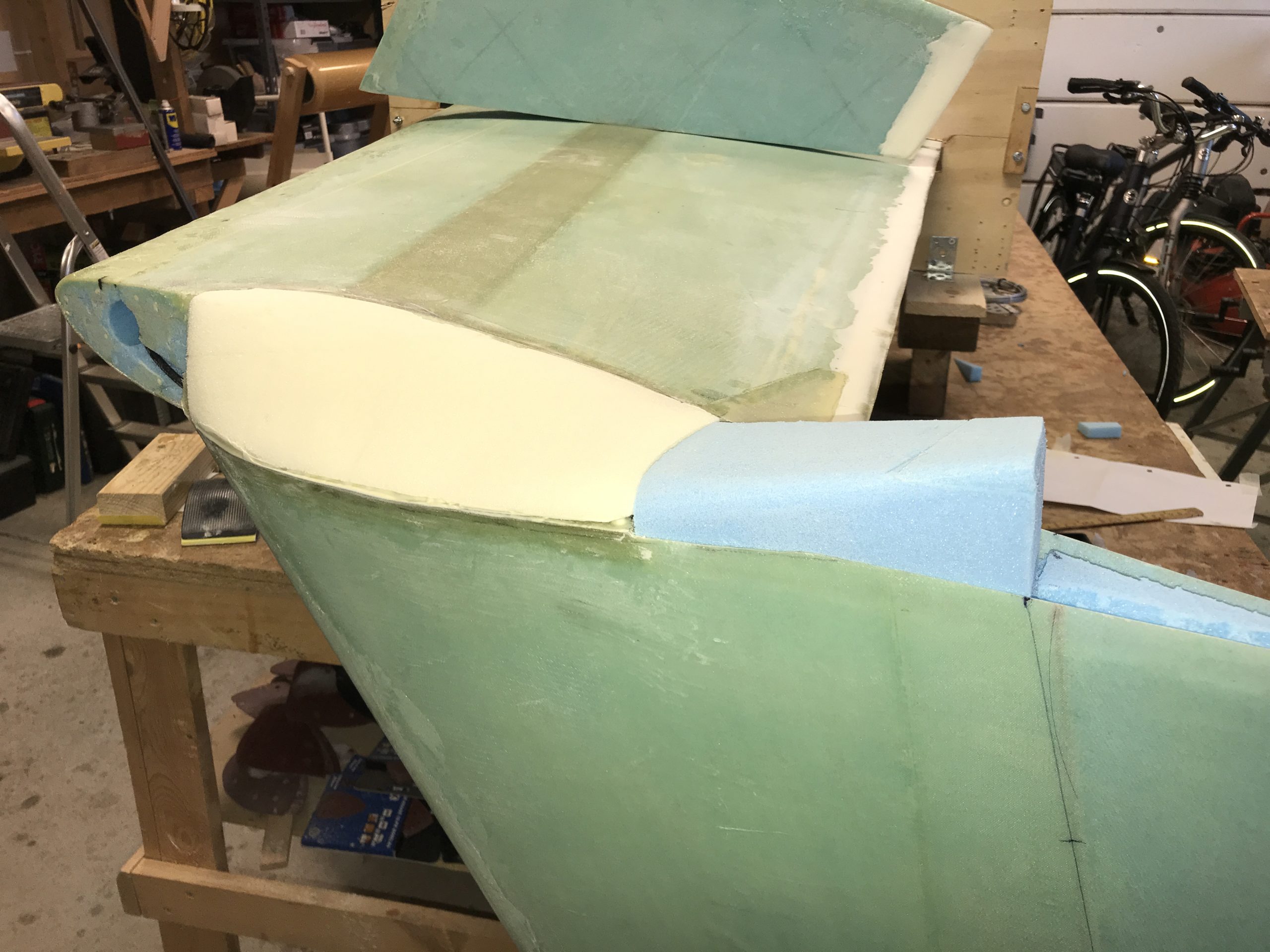
2019-11-24: Removed foam at the intersection between winglet and wing, as well as the other edges to get a good glass to glass bond.
The big question for me here was what to do with the rudder conduit when I am going to do the hidden bellhorns.

The plans for the hidden bellhorns does not describe this, and the pictures in the PDF are very difficult to interpret as they are B/W copies of a B/W paper. Luckily we have a great canard community online and I got some excellent guiding from Joe Polenek (no blog unfortunately), accompanied with great pictures showing how he did it. I did also read some of the builder blogs, especially Wayne Hicks. After some discussions I have ended up to follow Joes way and document it as I go on.
I had some email discussions with Joe regarding his method to understand what he did different than others. The biggest change is that this method attaches the bellhorn to the rudder perpendicular to the hinge line. He has made a pretty good writeup of what to do, it is located here. Not everything was obvious in that writeup either (at least not for me), so I will document my progress the usual way. I believe that this documentation together with Joes writeup would be a good help for others.
2019-12-01: Used my bandsaw to make the foam wedges.
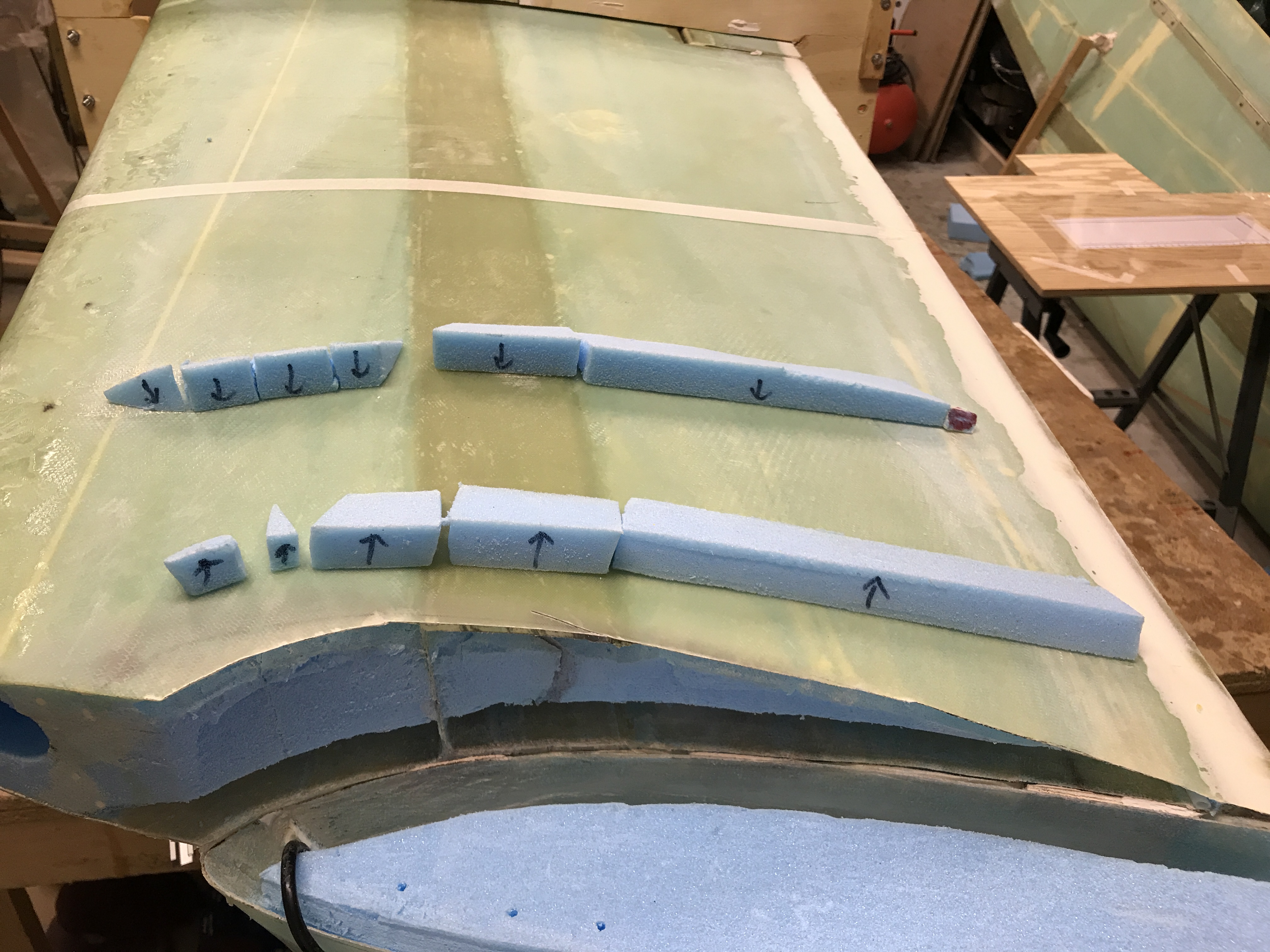
Then I glassed layup #1, and filled with flox and the foam wedges.
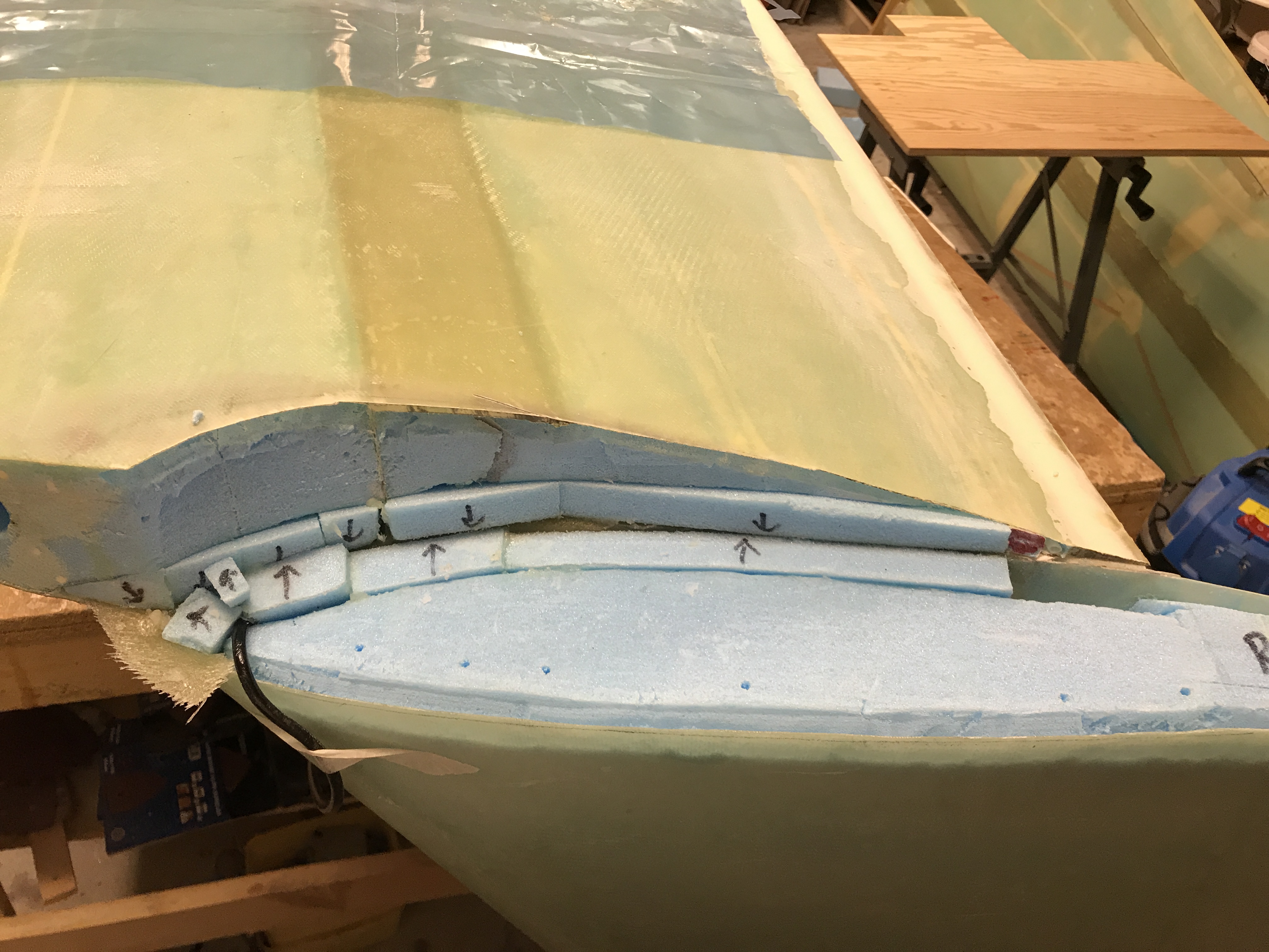
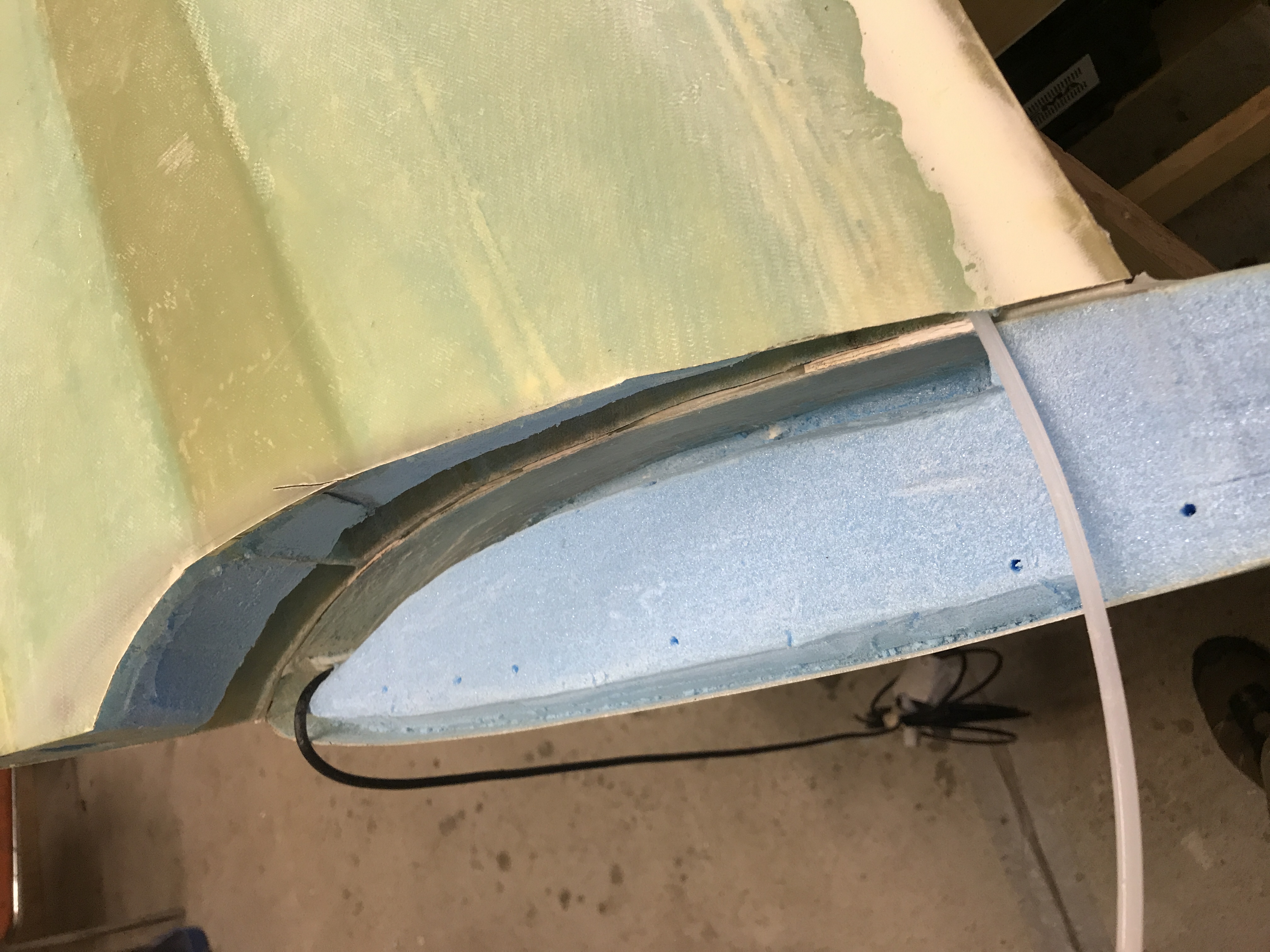
Notice that I have cut back the rudder conduit, which is a necessary step for the hidden bellhorn approach. I have also placed a sacrificial foam piece just beside the conduit here to make room for later steps.
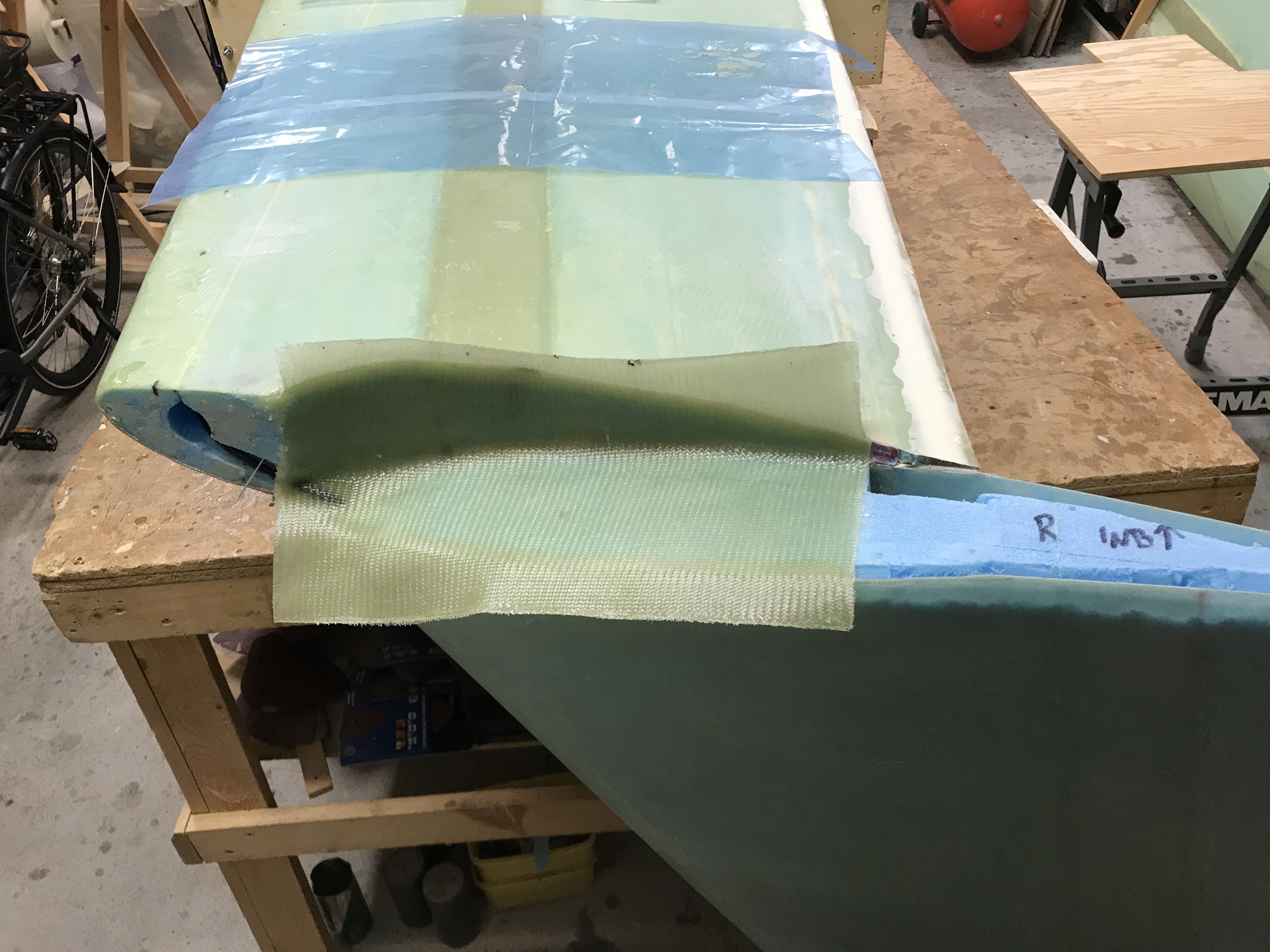
2019-12-02: Glassed layup #2. Here is also a diversion from the plans – the layup does not continue back to the aft of the winglet (2 plies). The next steps shows more of the changes due to internal bellhorns.
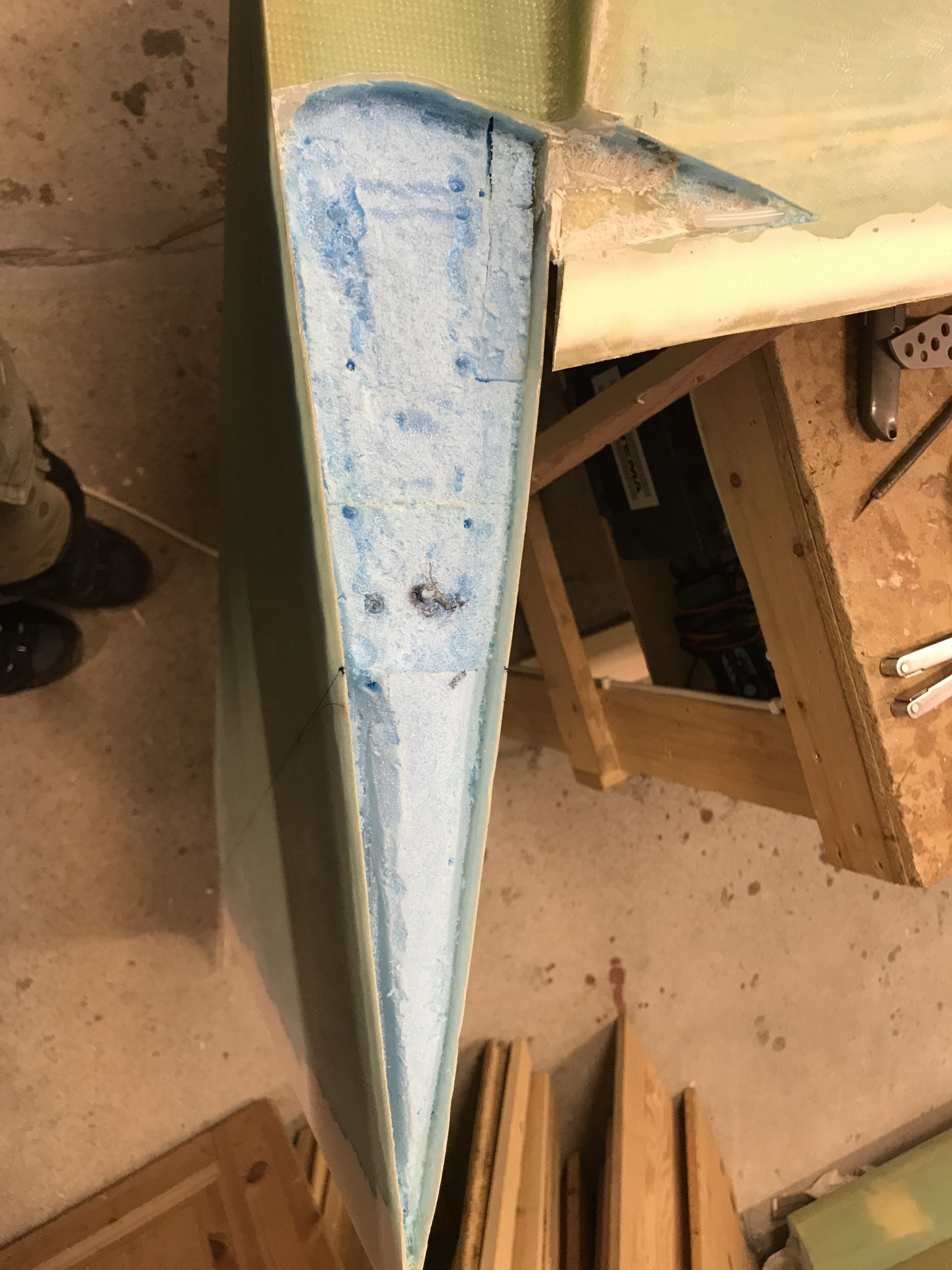
2020-03-22: These steps was done before I changed to Joes method. You will see that I actually cut back some of the wing skin over the rudder conduit, as well as shorten the conduit with two inches according to Joes plans.

Then I removed foam back to the rudder hinge line. This is neccessary to make room for the bellhorn movement:
Now it is time to make a foam plug that later would be removed after glassing. The cavity inside will be where the bellhorn moves. The angle of the plug follows the perpendicular line from the rudder hinge line as the paper template shows. I have also microed block A (urethane) to the winglet, and sanded it according to plans, as well as a small adjustment on the aft face of block A found in Joes plans.
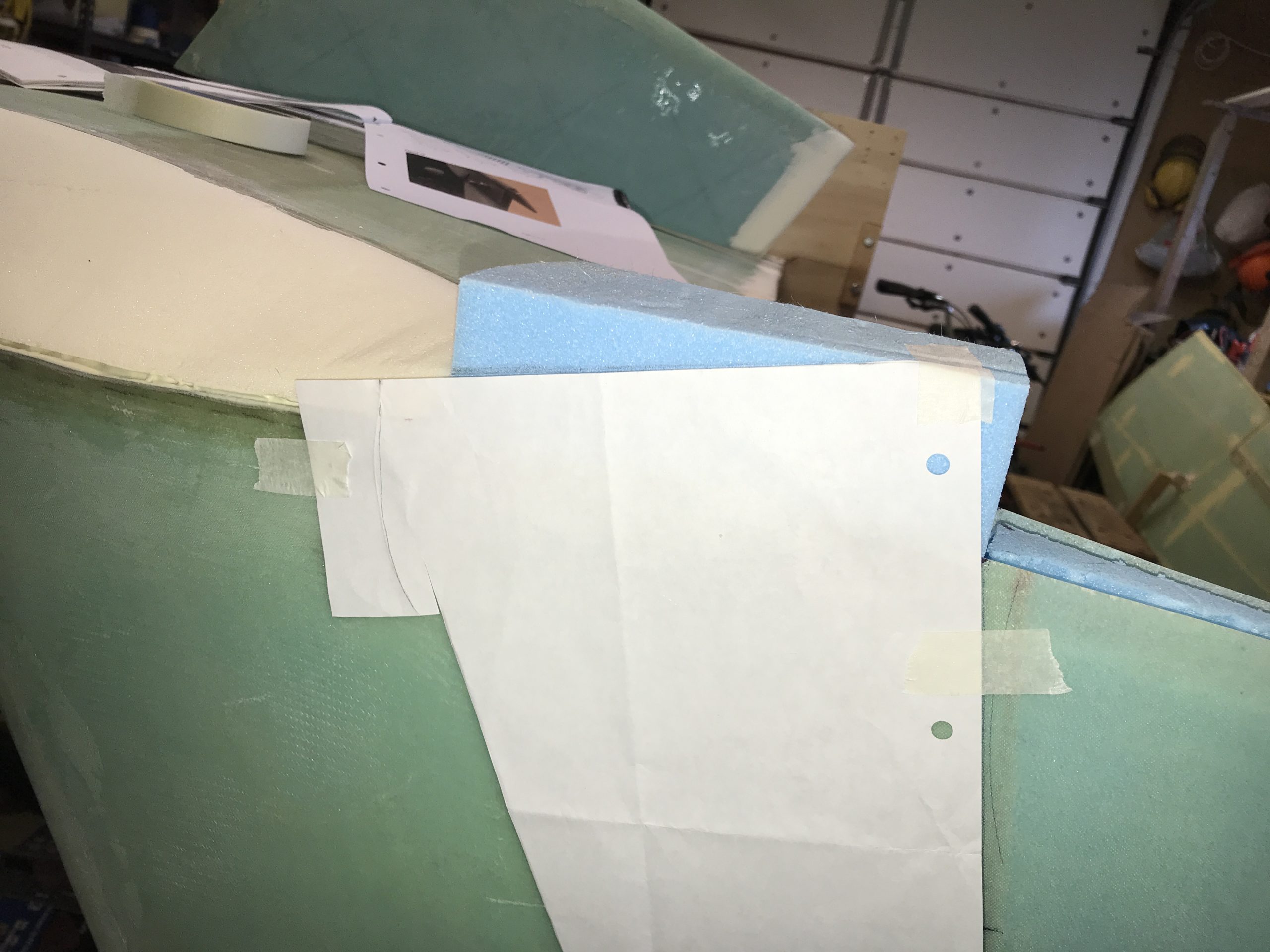
Then I sanded the plug to match block A. It is important to leave enough room or height in the junction between block A and the plug to make enough room for the bellhorn to move outwards.
I covered the block with electrical tap as a release agent, since I am removing the block later: