
In this step I will add some hardware to the aileron and wing.
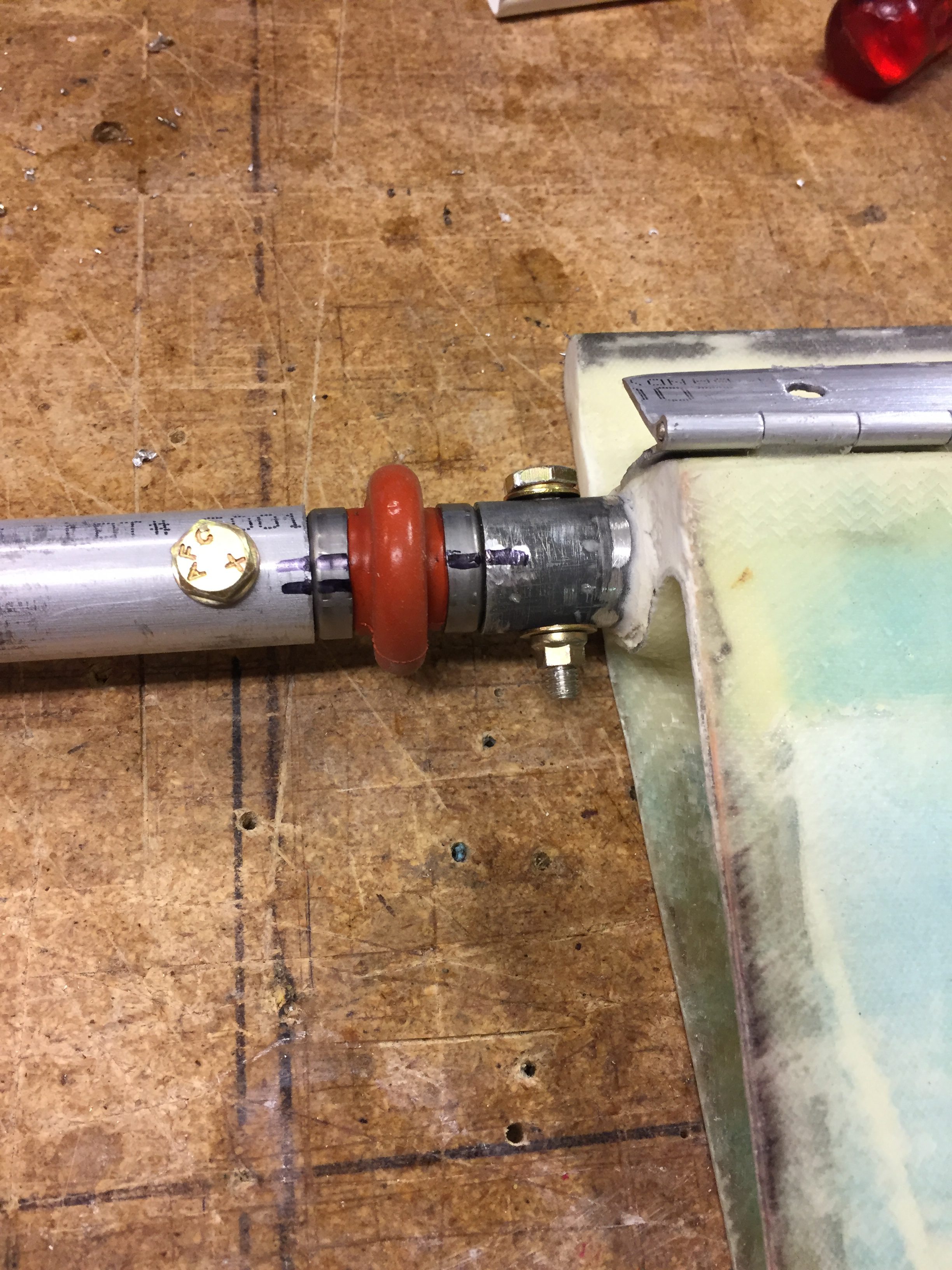
2017-04-12: I have marked the U-joint and the tubes to clearly indicate which side that goes where. When drilling through these tubes it’s almost impossible to drill a hole that is 100% symetric, so it’s important to mount the tubing and the joint the right way to ensure that the bolts go in place correctly.
The next step was to open up the hole in the wing root where the control tube is going from the aileron.
Note that I had to remove more glass and foam in the bottom to make room for the control arm that comes here.
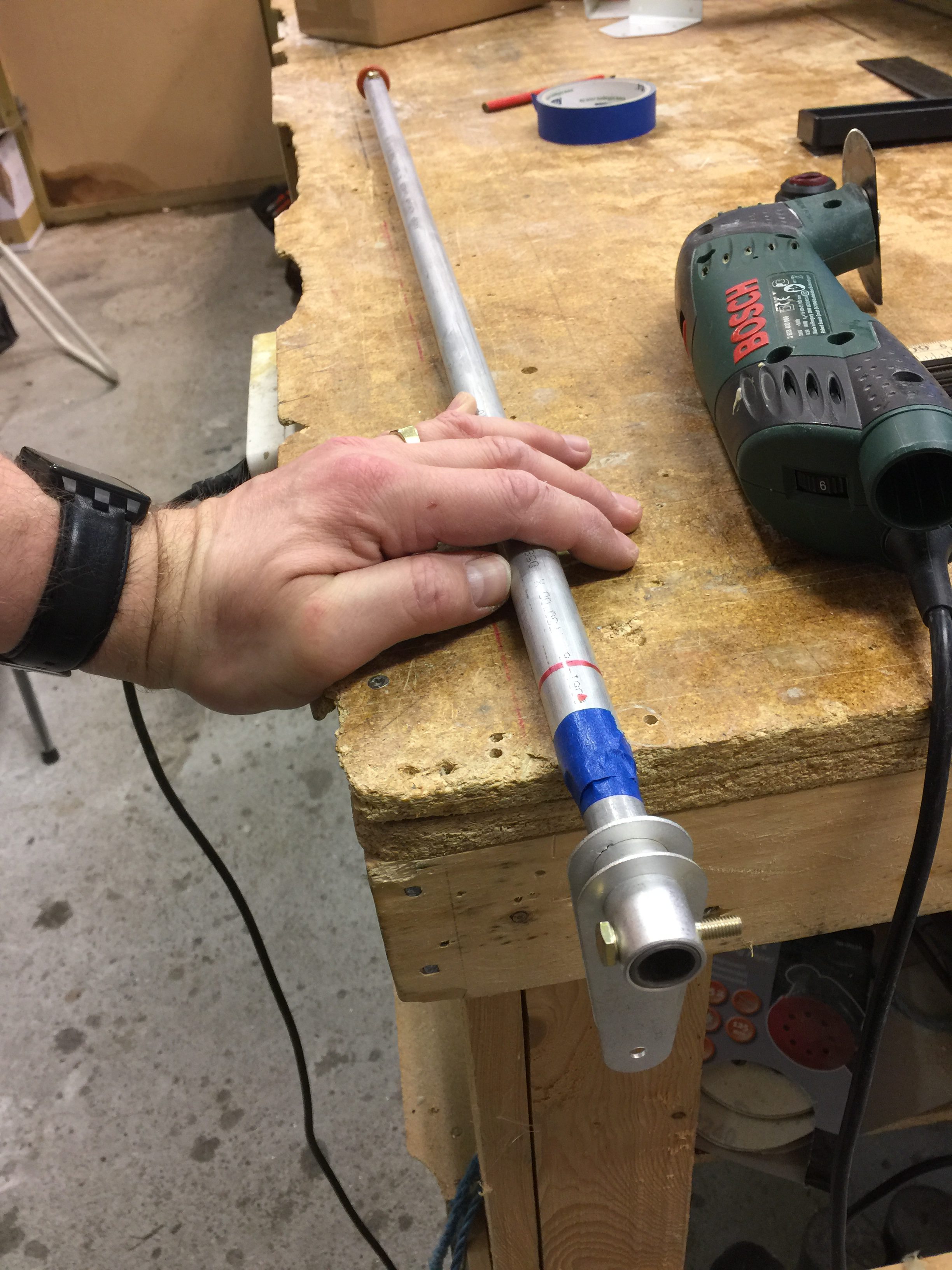
I measured the control tube from the aileron and the other hardware, and cut the tube off with a hacksaw.
Instead of using the plans phenolic block as a bearing for the control tube, I have instead changed to IGUS EFOI 10 R:
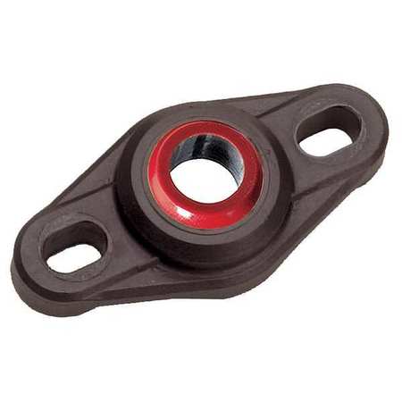
This is a proven change recommended from many and is well documented. I started by making a mounting plate for the bearing of a 8-ply BID plate I had made for ages ago.
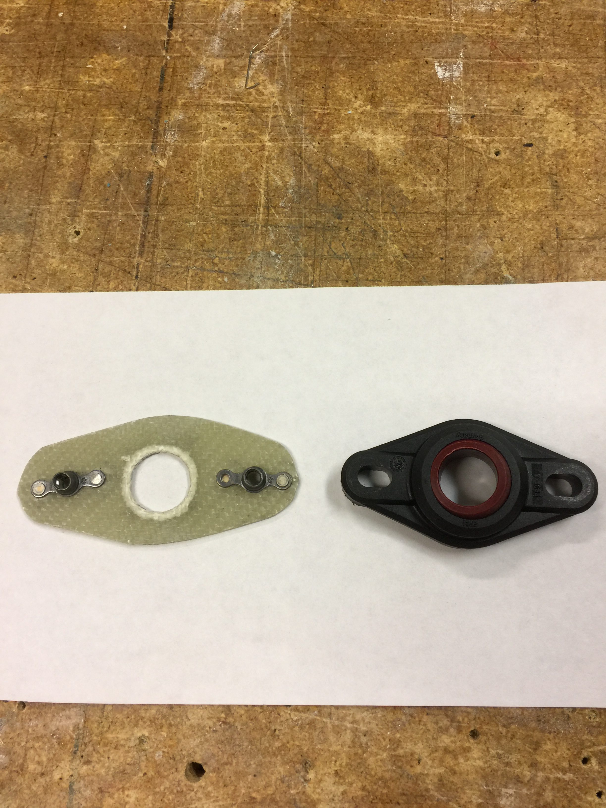
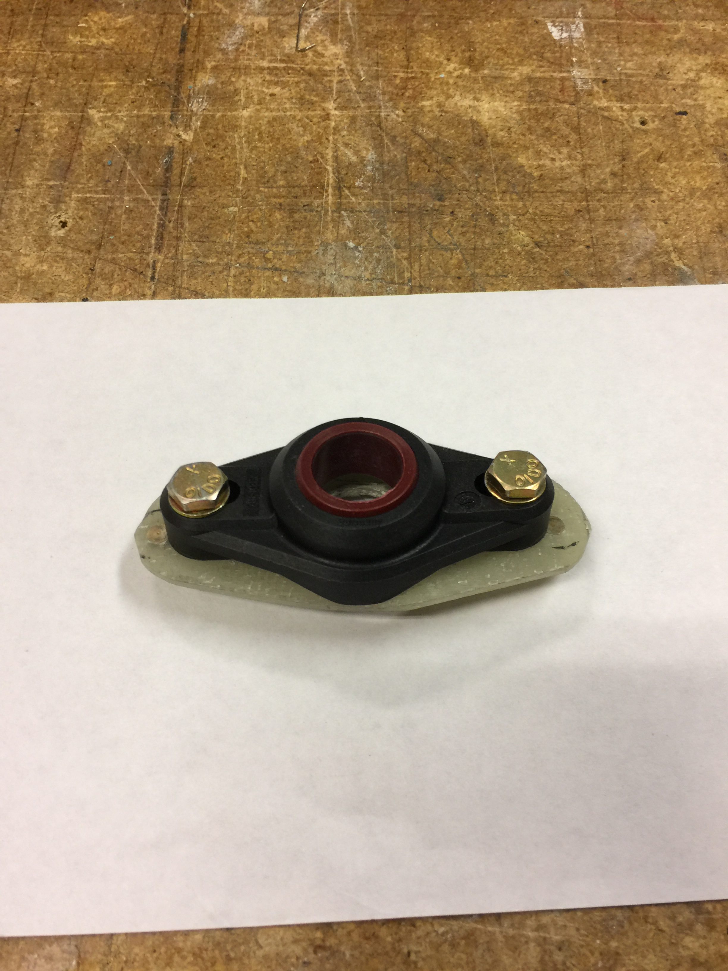
I riveted on a couple of nut plates. The assembly looks like this:
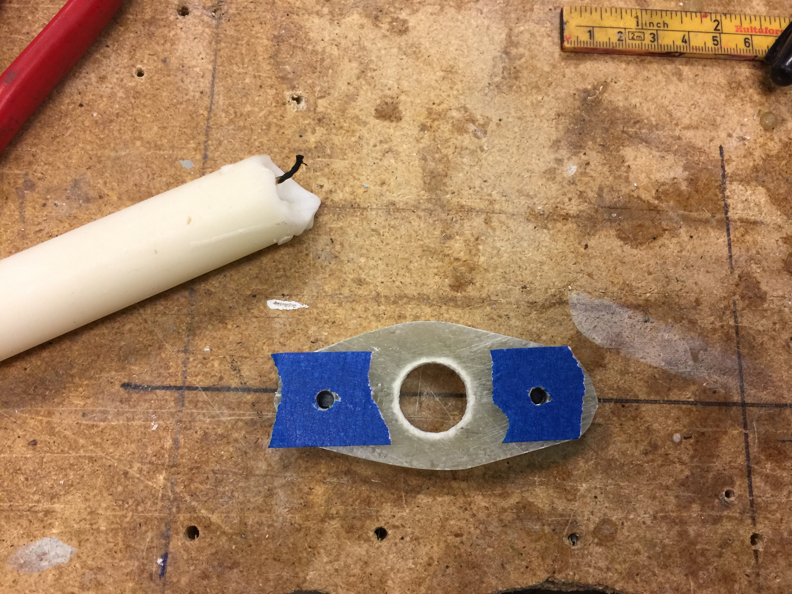
Before glassing the plate to the wing root I filled the hole for the bolt with candle wax to avoid epoxy in the hole.
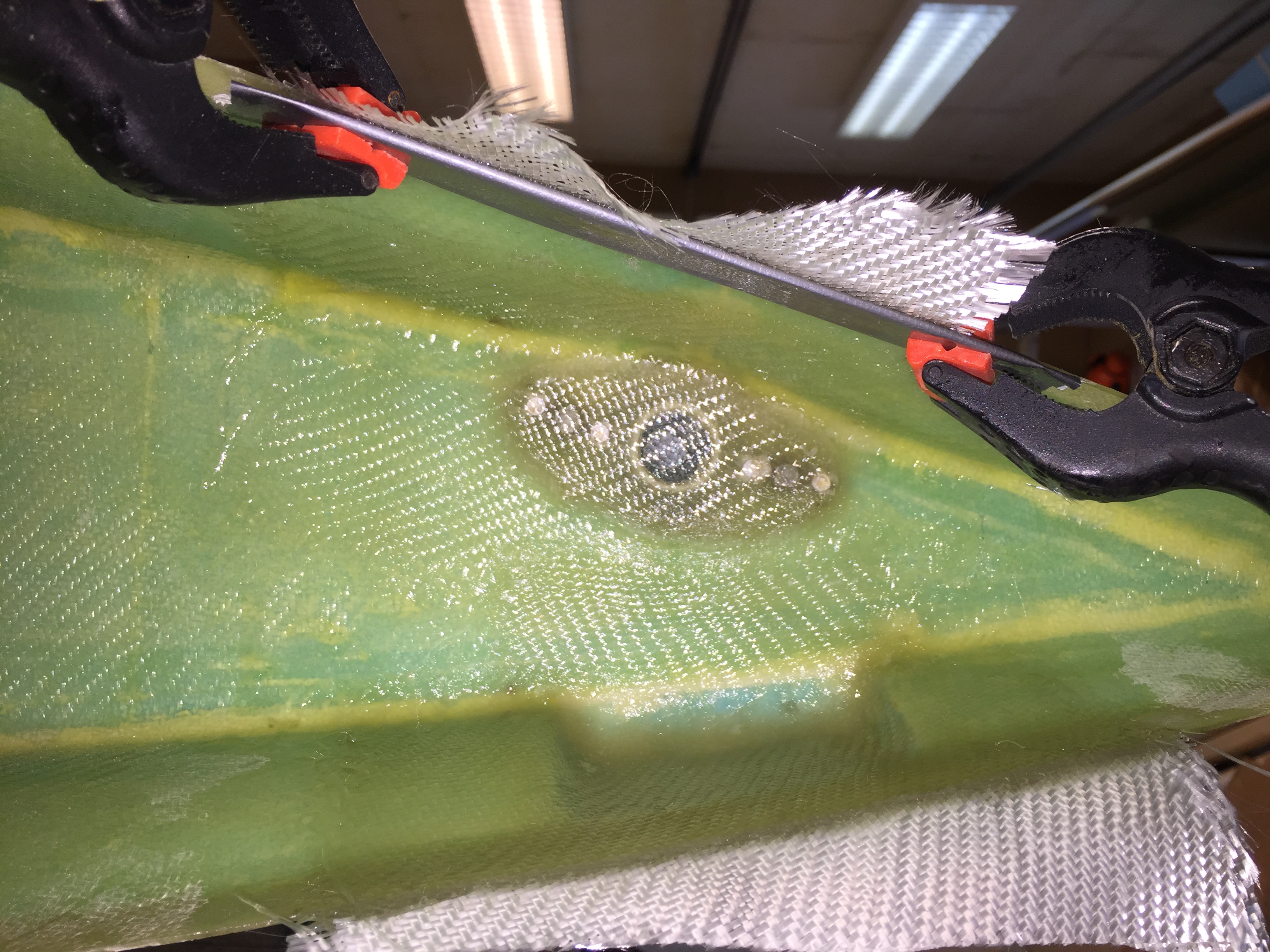
Finally I glassed the plate in place with 2 plies of BID and also added extra reinforcements where I removed glass and foam.
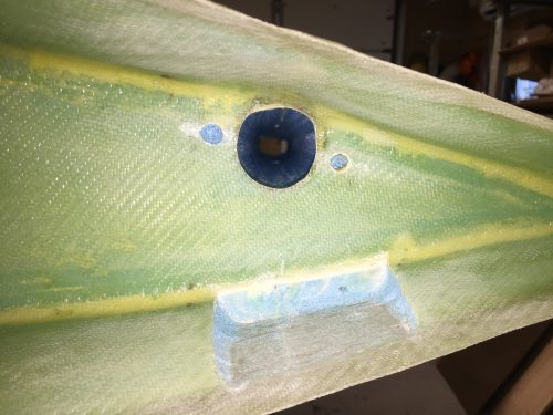
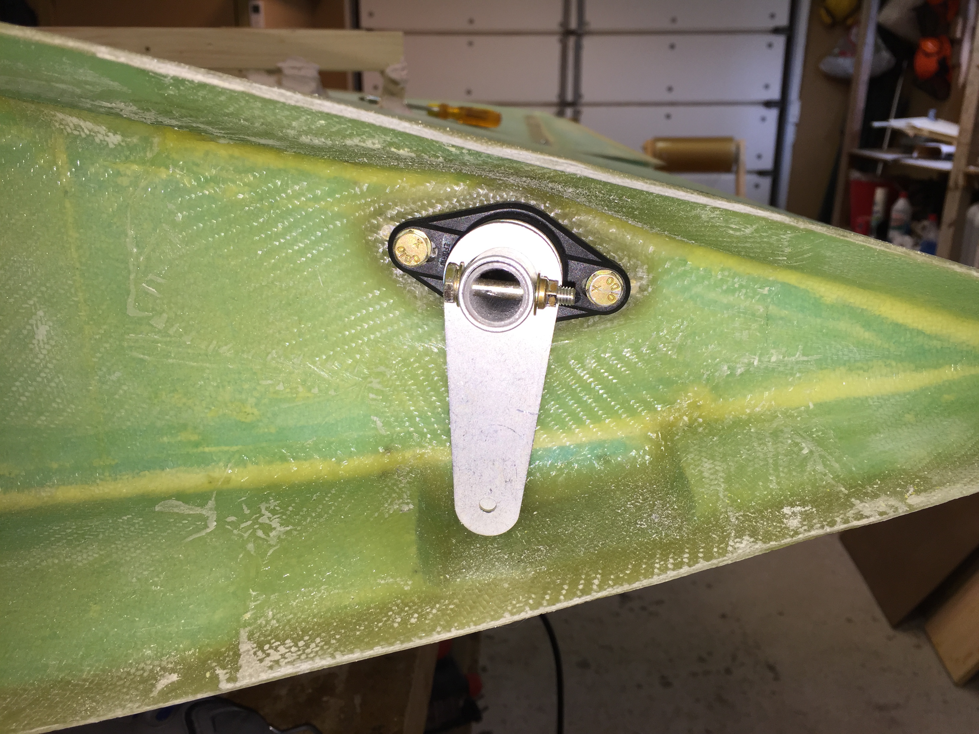
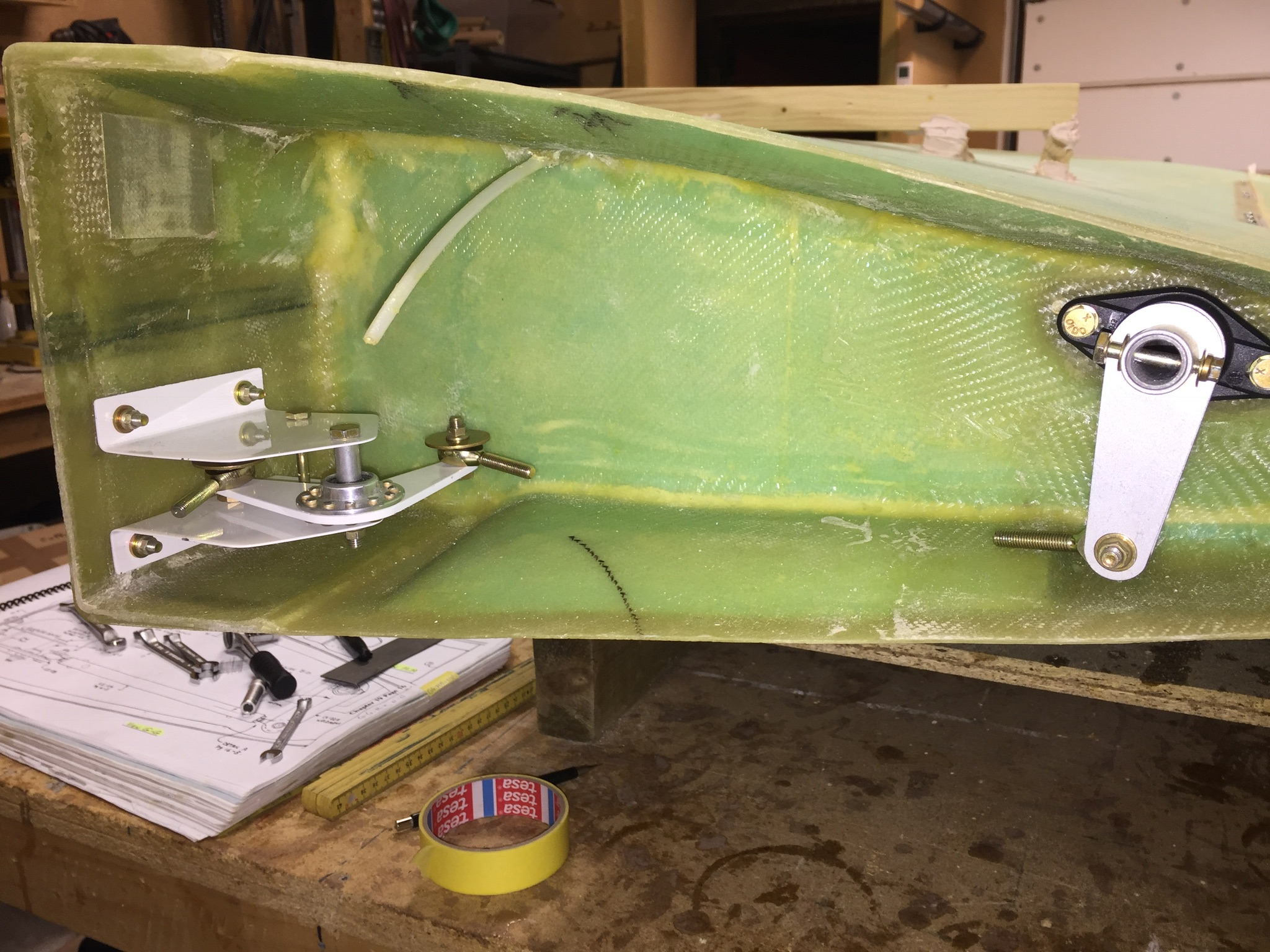
2017-04-13: here the bearing is mounted:

And the bellcrank is bolted to the torque tube.
2017-10-28: After a long break due to an accident at May 6th where I fell down from a ladder and fractured my wrist and calcaneus (heel bone), I’m finally back in business!
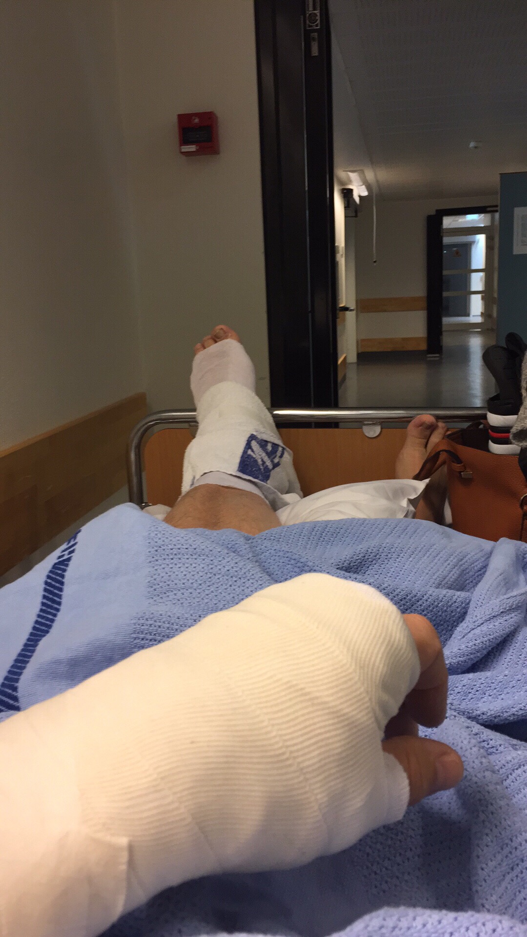
I don’t think the new hardware in my body are aircraft grade, but it doesn’t sound any alarms when I go through the security scan on the airports. 7 screws in my heel and 13 screws and an insert of some kind in my wrist.

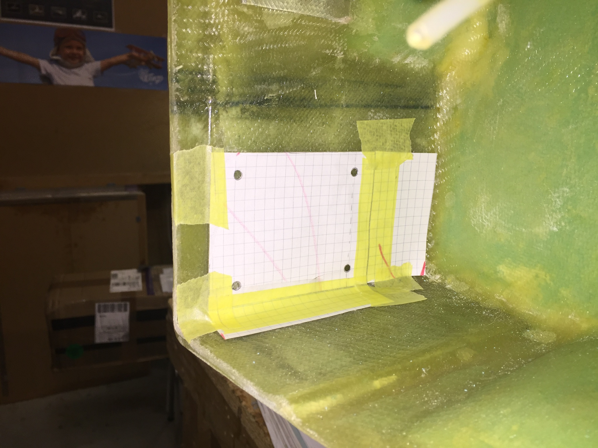
To fasten the brackets, I made a paper template to get the holes at the right place.
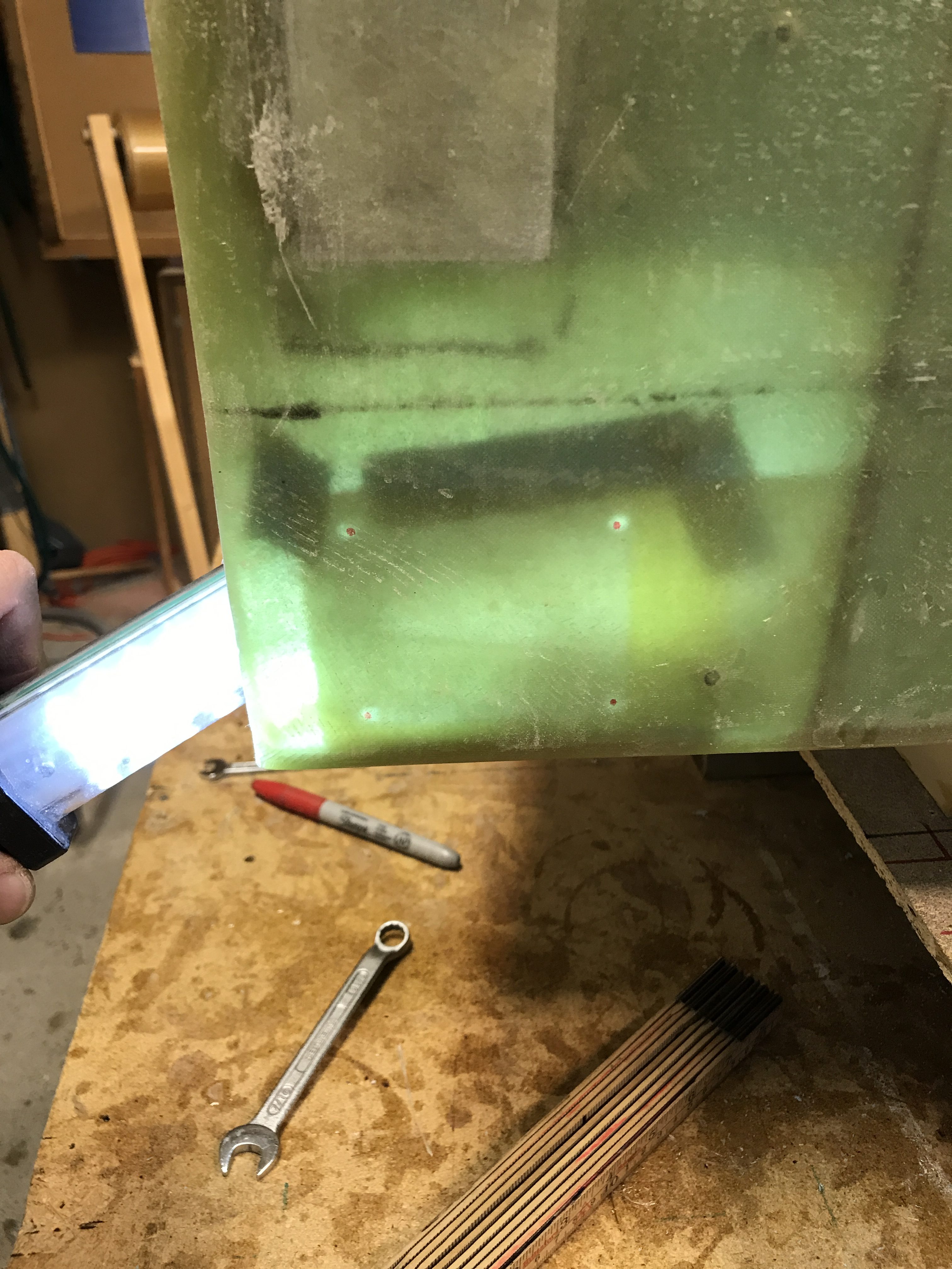
This is how it looks like with some backlight (this is from the left wing).
Then I mounted the bracket with all the accessories. I must admit – I had to think over this more than one time to get this right.
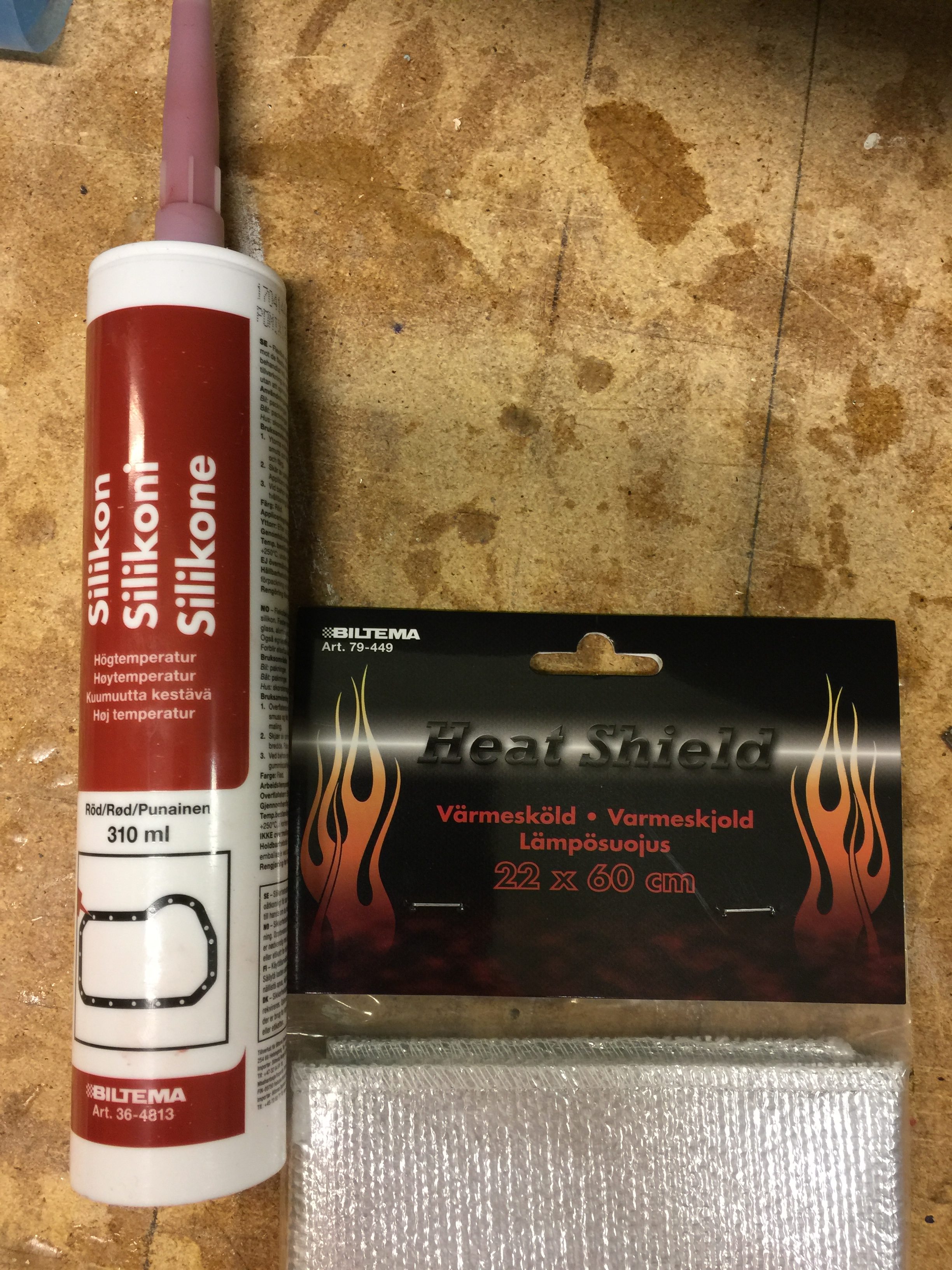
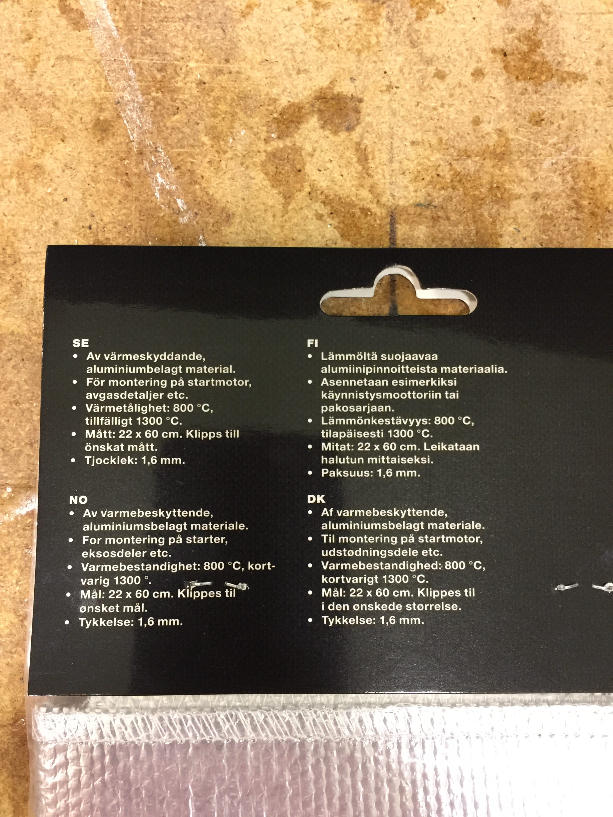
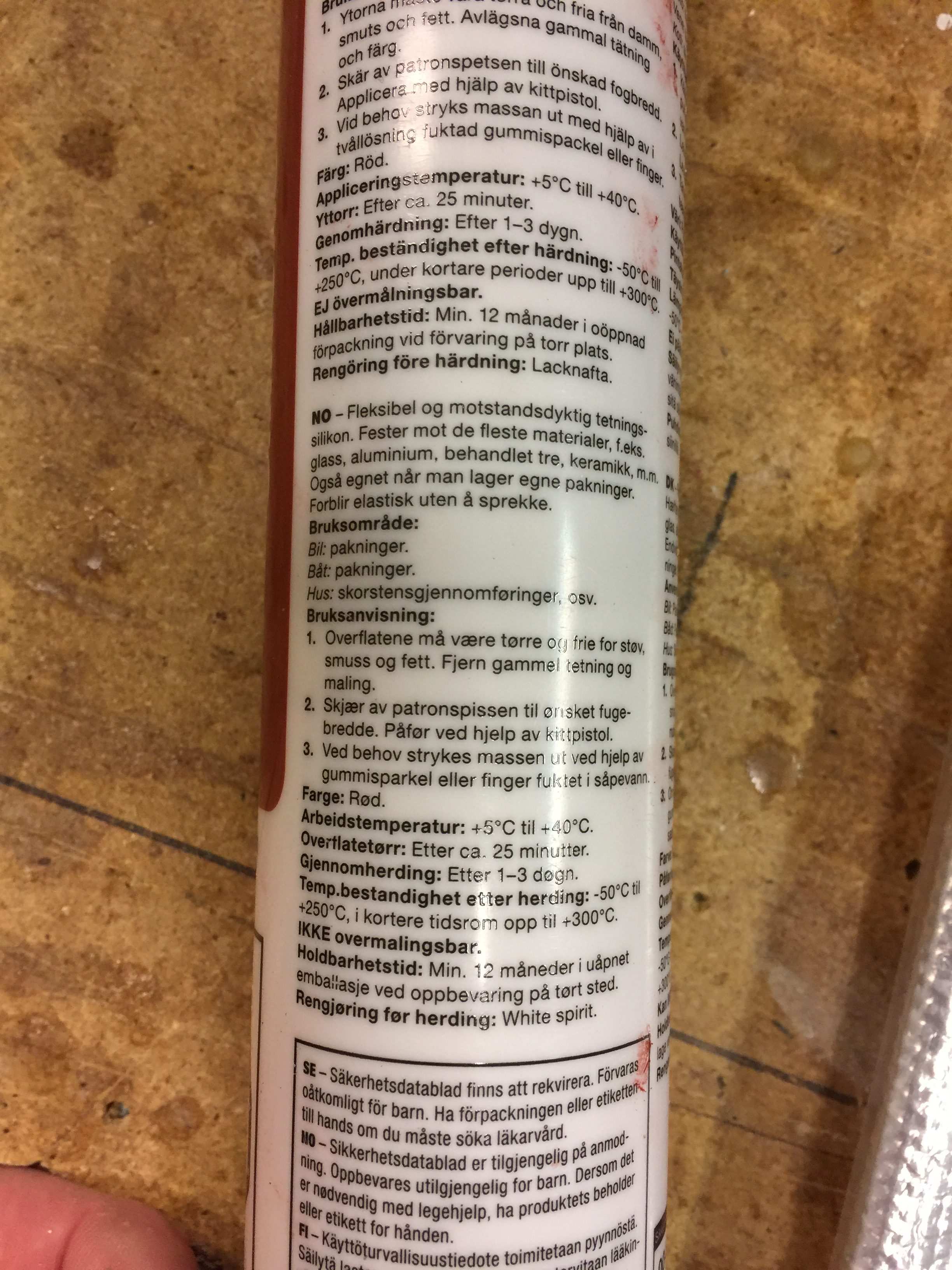
2017-11-05: Before I store away the right wing I decided to add the heat shielding. I copied how James Redmond did it on his Berkut (Race 13), using heat resistant aluminum foil backed by some heat resistant fabric. This is rated for 800 degrees C/1472 F and 1300C/2372F for short periods. I glued this to the surface with high temp heat restistant silicon rated for 250C/482F and 300C/572F for short periods.
Started by removing all hardware and making paper templates of all the surfaces.
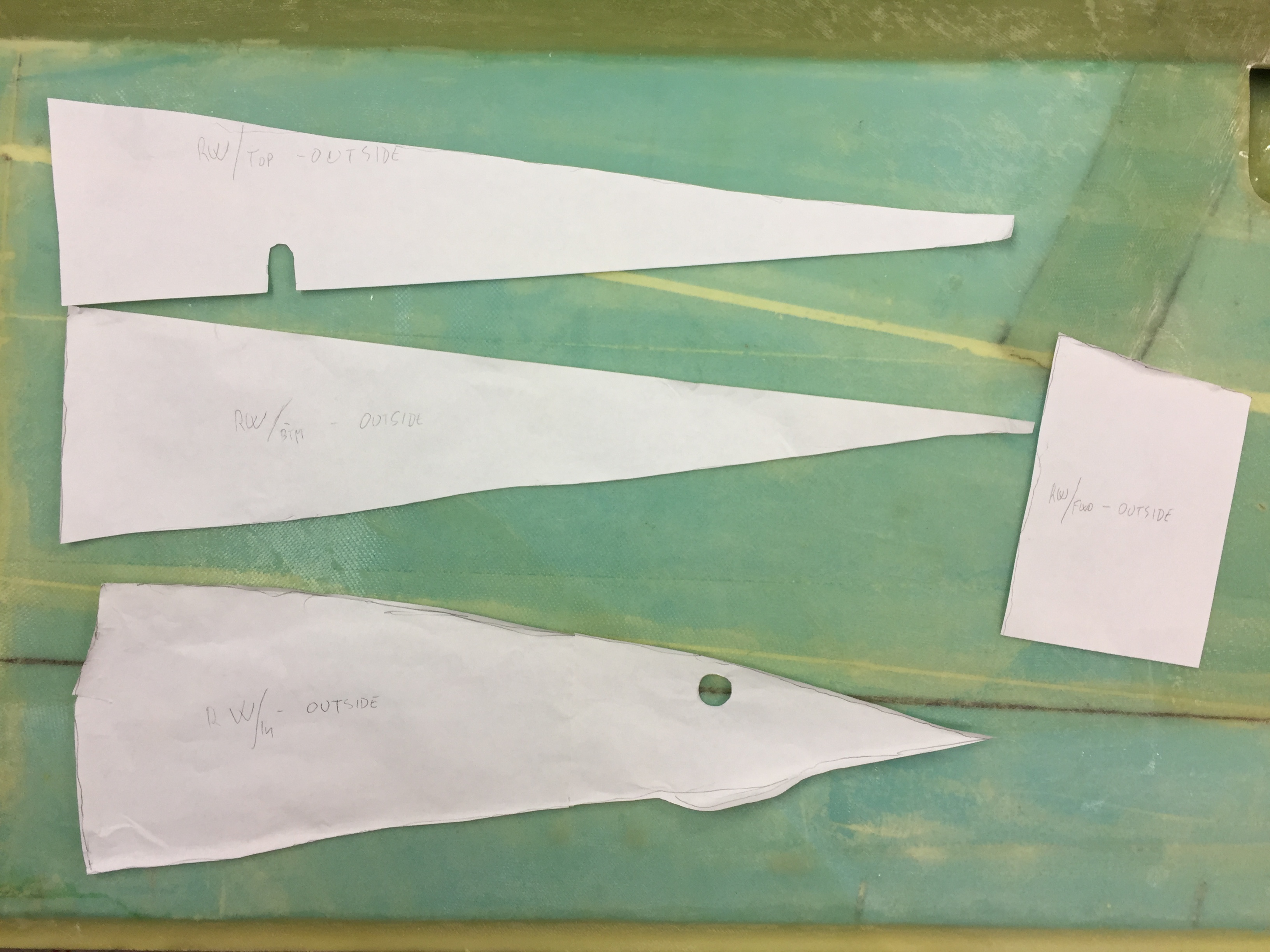
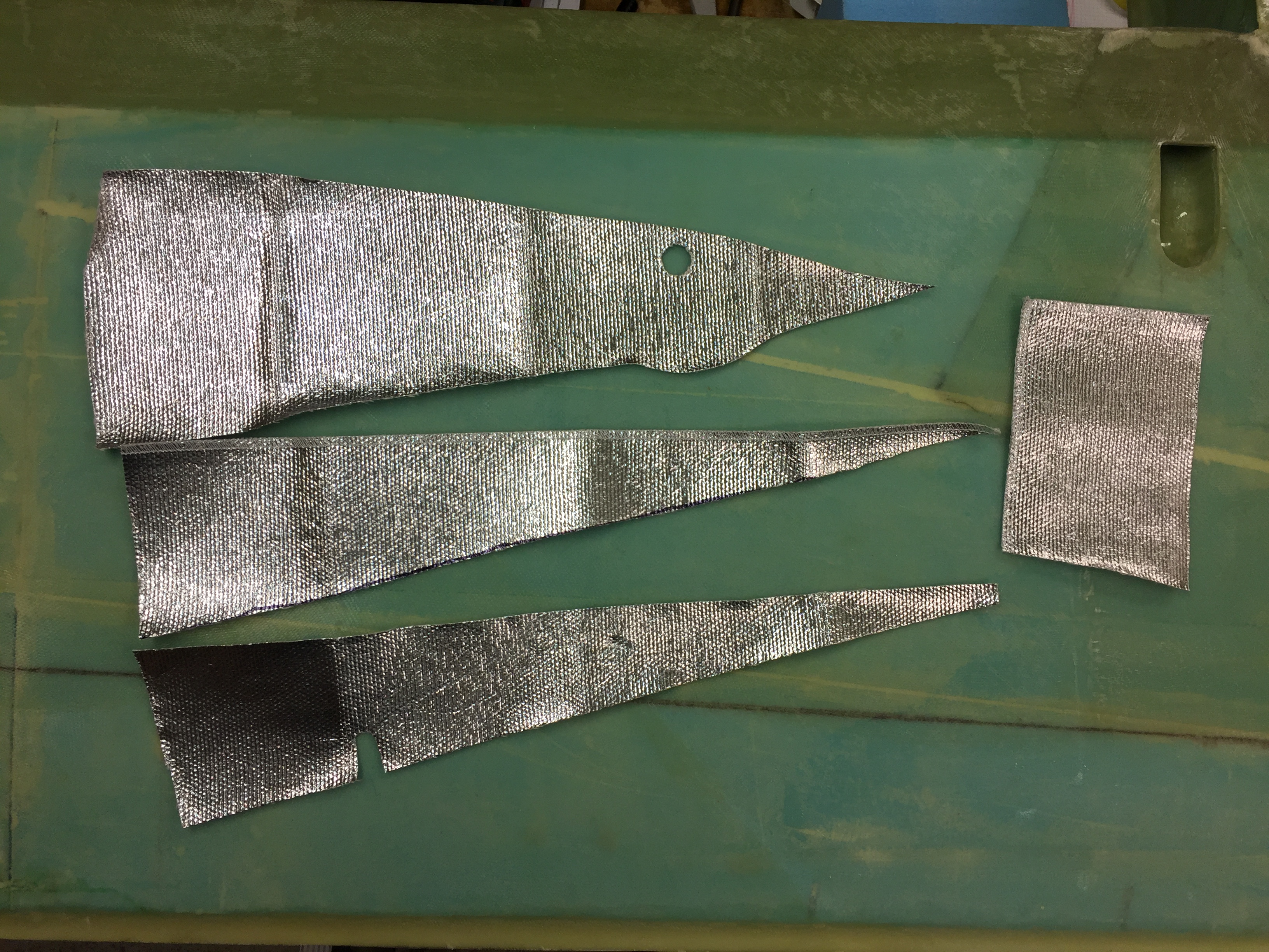
Then I transfered them to the heat shielding and cut them out.
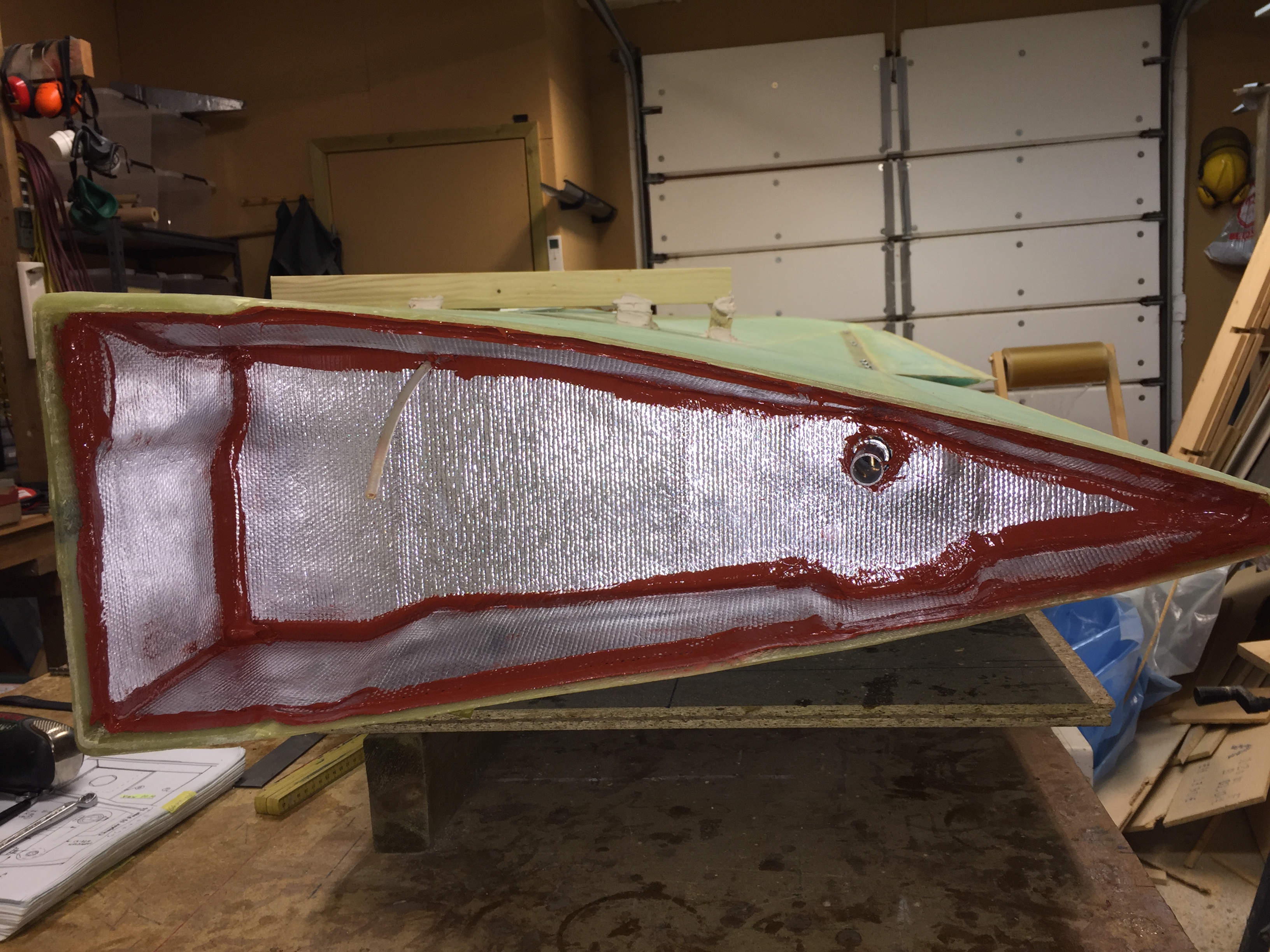
Covered the surface with silicone.

And glued the aluminum to the surface. I also filled all the joints with silicone. Turned out pretty good.
2017-11-09: After curing of the silicone I remounted the hardware, including the steel rod with inserts, properly riveted. Be aware of that the position of the rivets for the inserts showed in the drawing in chapter 19, does not correlate with the new inserts from the Cozy Girrrls. You need to move the rivets further aft of the inserts so that the Aurora Bearings can be screwed all the way down in the insert.

Here is a short video showing how the mechanics works: