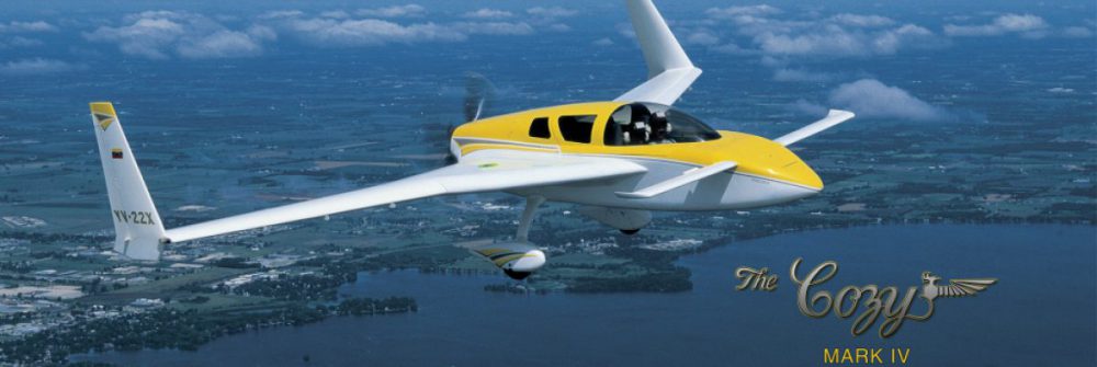
2016-10-16: After sanding and tidying up after glassing the top spar cap, I started step 8 by removing the fishtail first. This is because the conduit adapted for the hidden bellhorns comes in conflict with the fishtail on the outboard end. Removing the peel ply was not as easy as the plans said. I remember reading about other having the same problem as well.I managed to remove it with quite some struggle. It resulted in some deep ridges on the foam nearby the trailing edge. I will fill this with flox I think right before I glass the top skin.
I also Dremeled the conduit for the Nyloaflow tubing to the rudders. As I am installing the hidden bellhorns I need to route the conduit a bit different on the outboard end. Everything is explained at Marc Z’s website. Glued the tubing with some 5 min epoxy.
Hindsight #1 – after cutting out the aileron I realized that I placed the Nylaflow conduit almost to close to the aileron cutout. For the left wing I placed the conduit one centimeter more away from the aileron.
Hindsight #2 – a new method of implementing the hidden bellhorns surfaced after I finished the wing. For this step the only thing one need to know is that the rudder conduit in the wing tip can be cut flush to the foam, as it will be cut back even further in chapter 20.
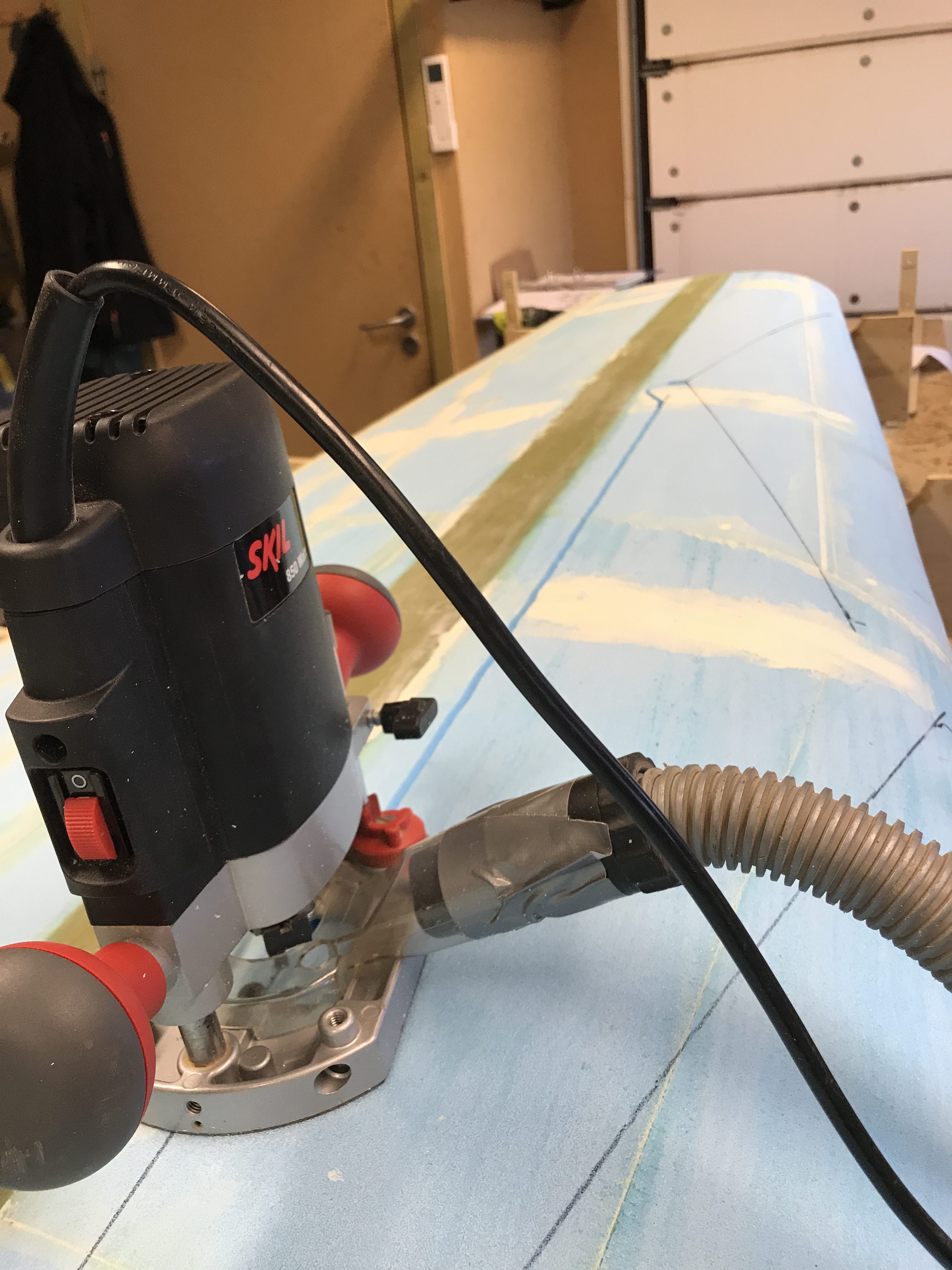
2019-02-24: Left wing: I forgot to add a VOR-antenna in the right wing. I planned to place one VOR-antenna in each wing (inspired by Charles Furnweger). I then decided to put two antennas in the left wing. There is adequate place for both of them in the same wing.

I made the antennas using copper tape, RG-58 coax and three ferrite toroids.
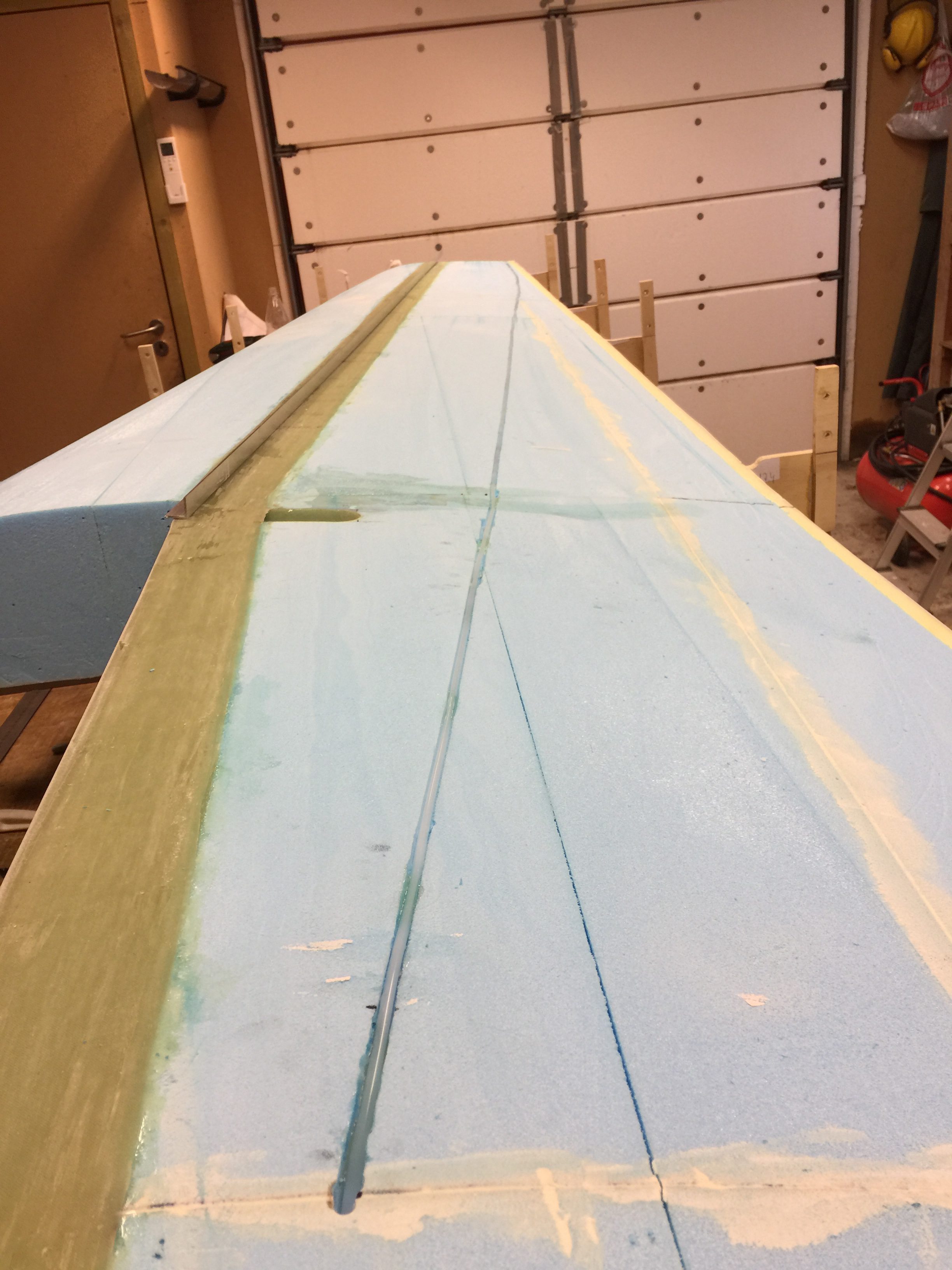
Routed two conduits for the coax cable using a 6mm straight router bit. Works like a dream – great to have it connected to my shop vacuum cleaner.
Recessed the connection part of the antenna in the foam using my Dremel.
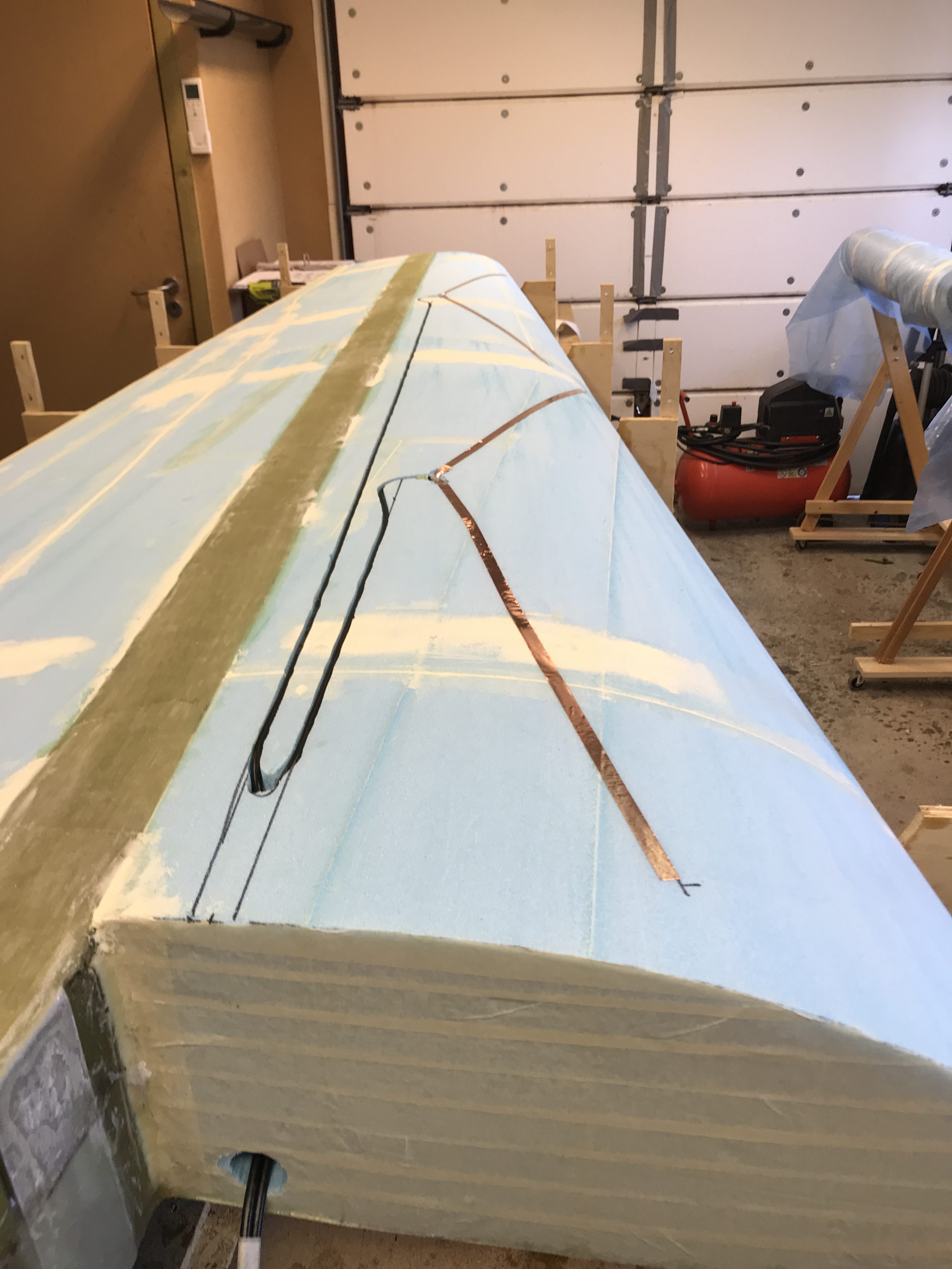
I drilled a hole down to the conduit for the electrical cables and pulled the coax through there.
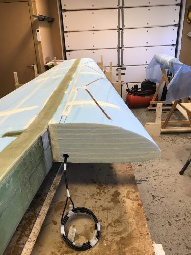
Finally I filled the coax-conduit with dry micro. I also marked the coax properly so I know which cable that goes to the inboard and outboard antenna. Right now I dont know where the connector to the antenna will be placed so I left a good part of coax here.
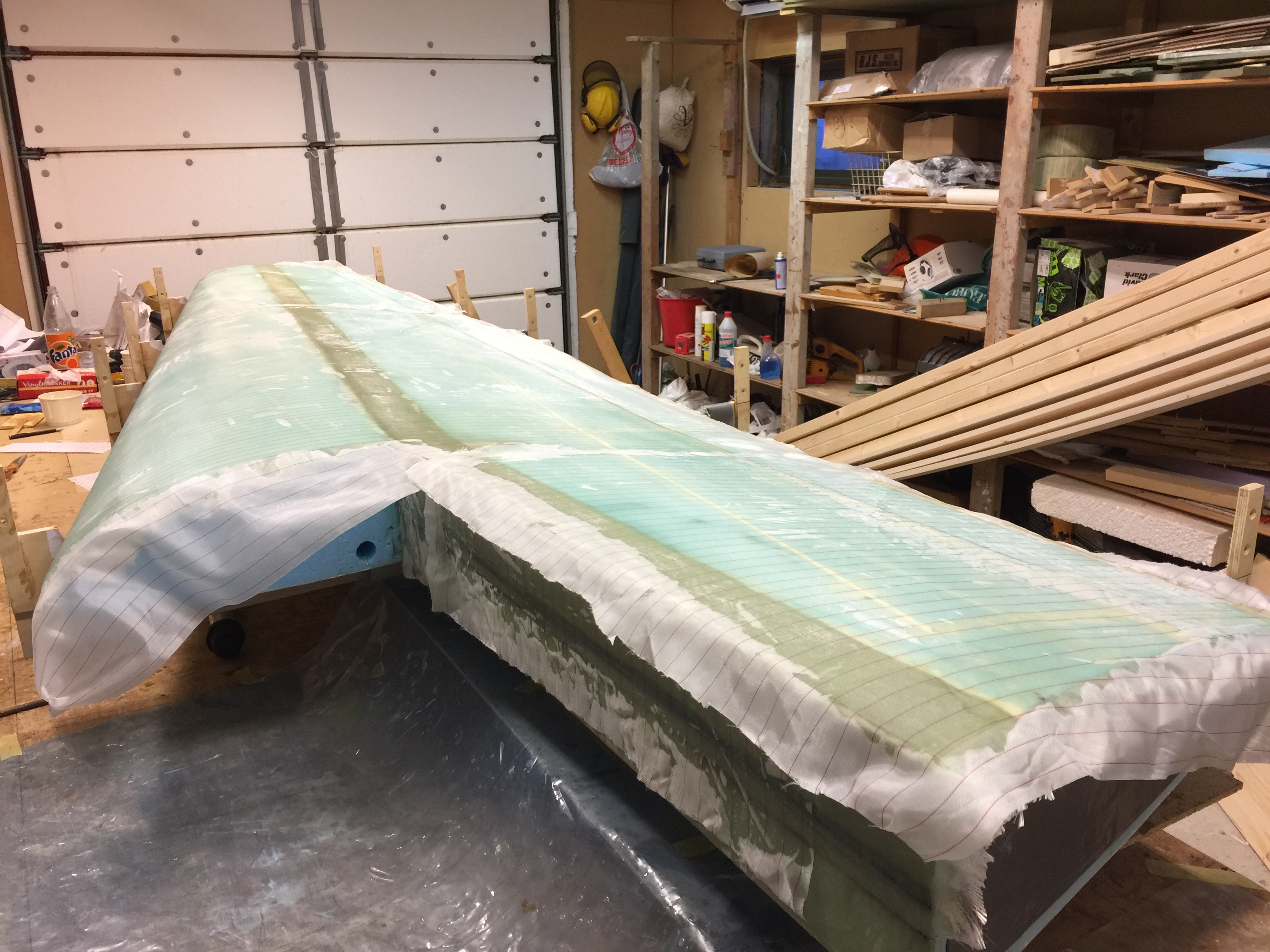
2016-10-22: Started to glass the top skin. After the first ply I realized I was short of UNI! Bummer… I managed to glass half of the second ply before I had to peel ply everything and order more UNI.
 To ensure that the soft trailing edge gets straight I had purchased an aluminum angle which I covered with duct tape and then clamped over the trailing edge on top of the peel ply.
2016-12-27: After two months I finally found some time to finish the top skin. I removed the peel ply, brushed on some epoxy and added the remaining UNI and all the small patches of UNI and BID. Peel plied everything and set to cure.
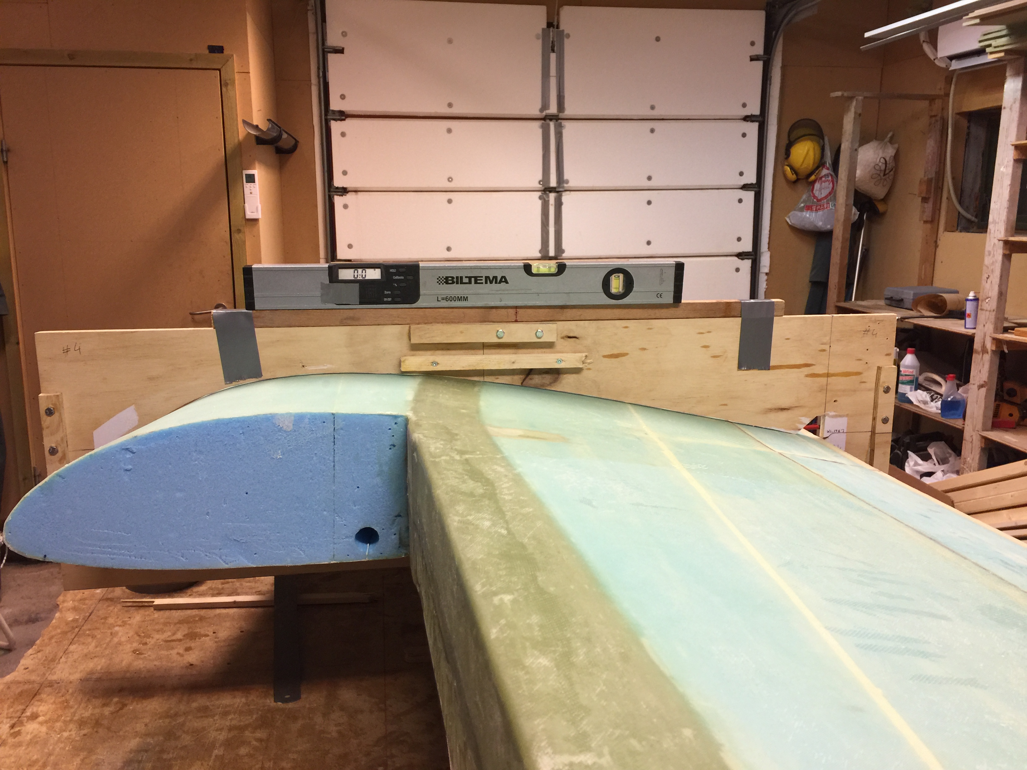
2016-12-29: After cure I removed the peel ply and trimmed all the edges. Then I reinstalled the top wing jig (#4). I had to trim it a bit since it was too tight after the foam was glassed. Then I shimmed the wing so that the jig was level. I also reinstalled jig #2 and checked the alignment here. It was level as it should be (phew!).
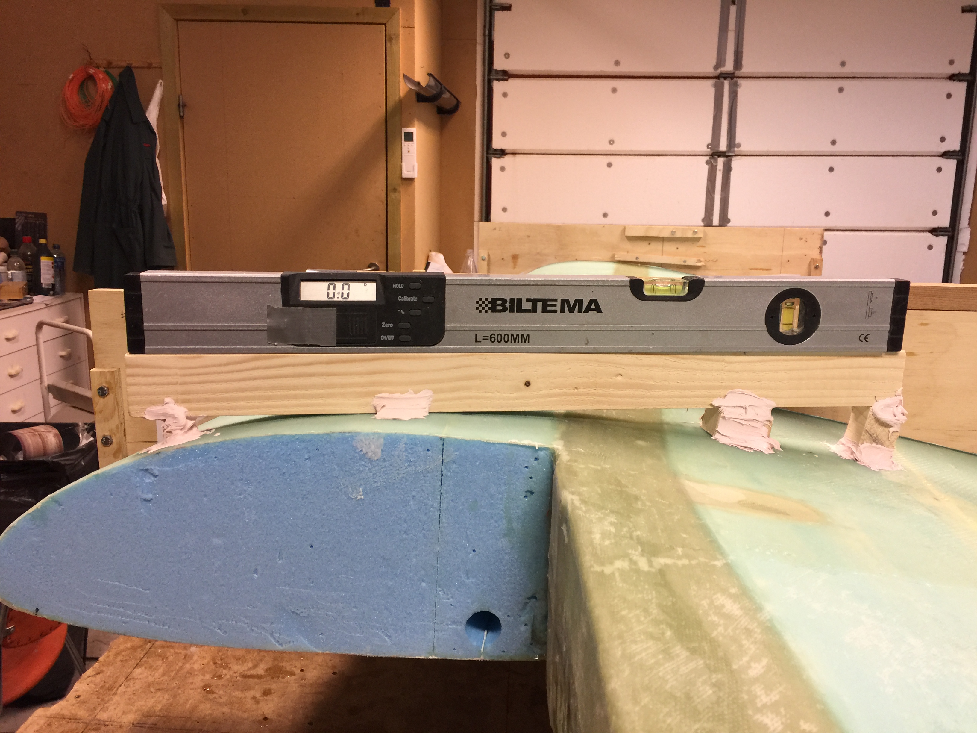
Finally in this step I bondoed a straight 2 feet long piece of wood parallell to butt line 67.5. This wood has to be level as well as this will be the reference when mounting the wings to the spar.
2019-03-03: Working on the left wing, finally glassed the top skin with good help from my wife.
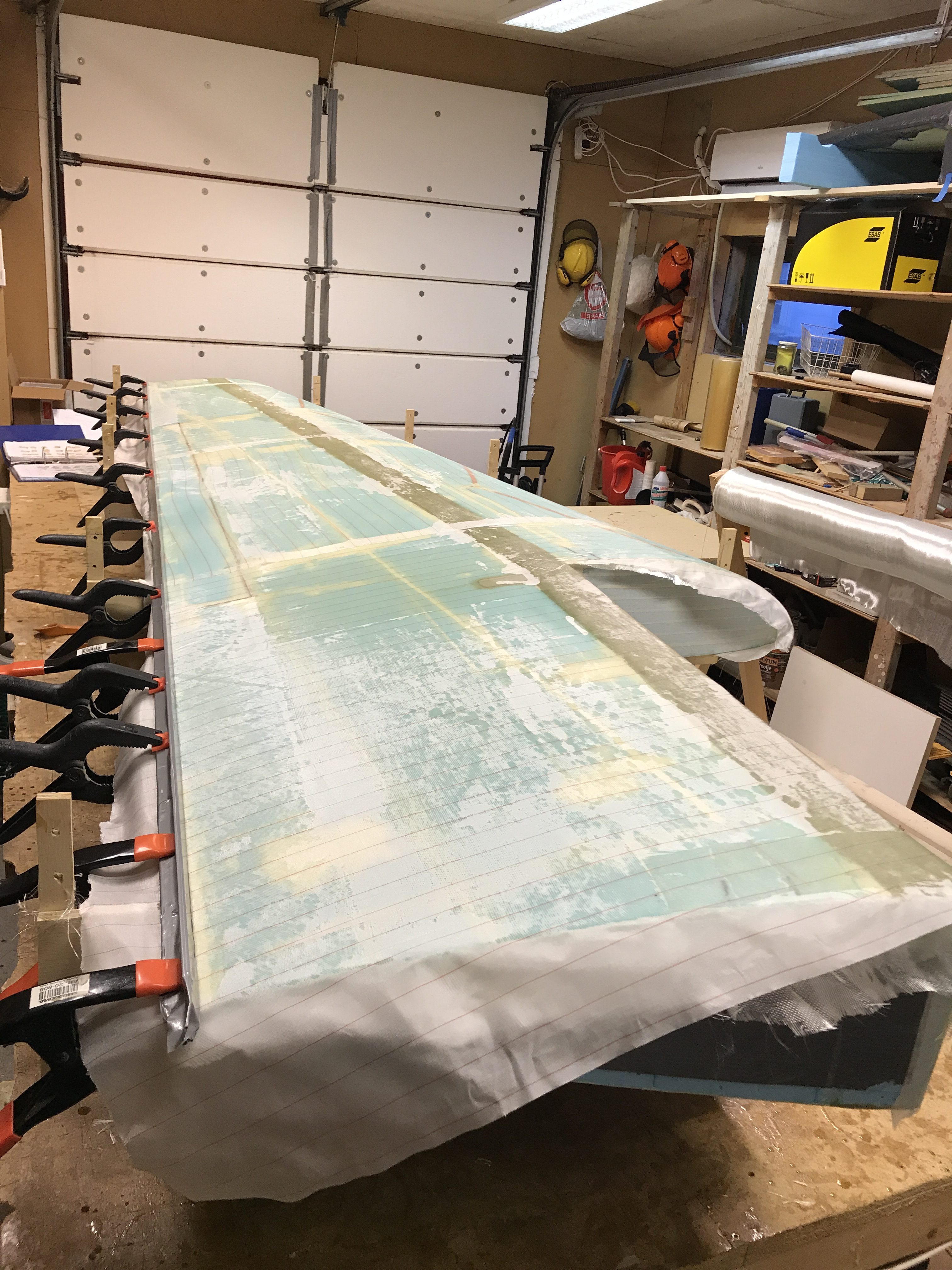
2019-03-09: And bondoed the high tech horizontal reference wood piece to the wing.
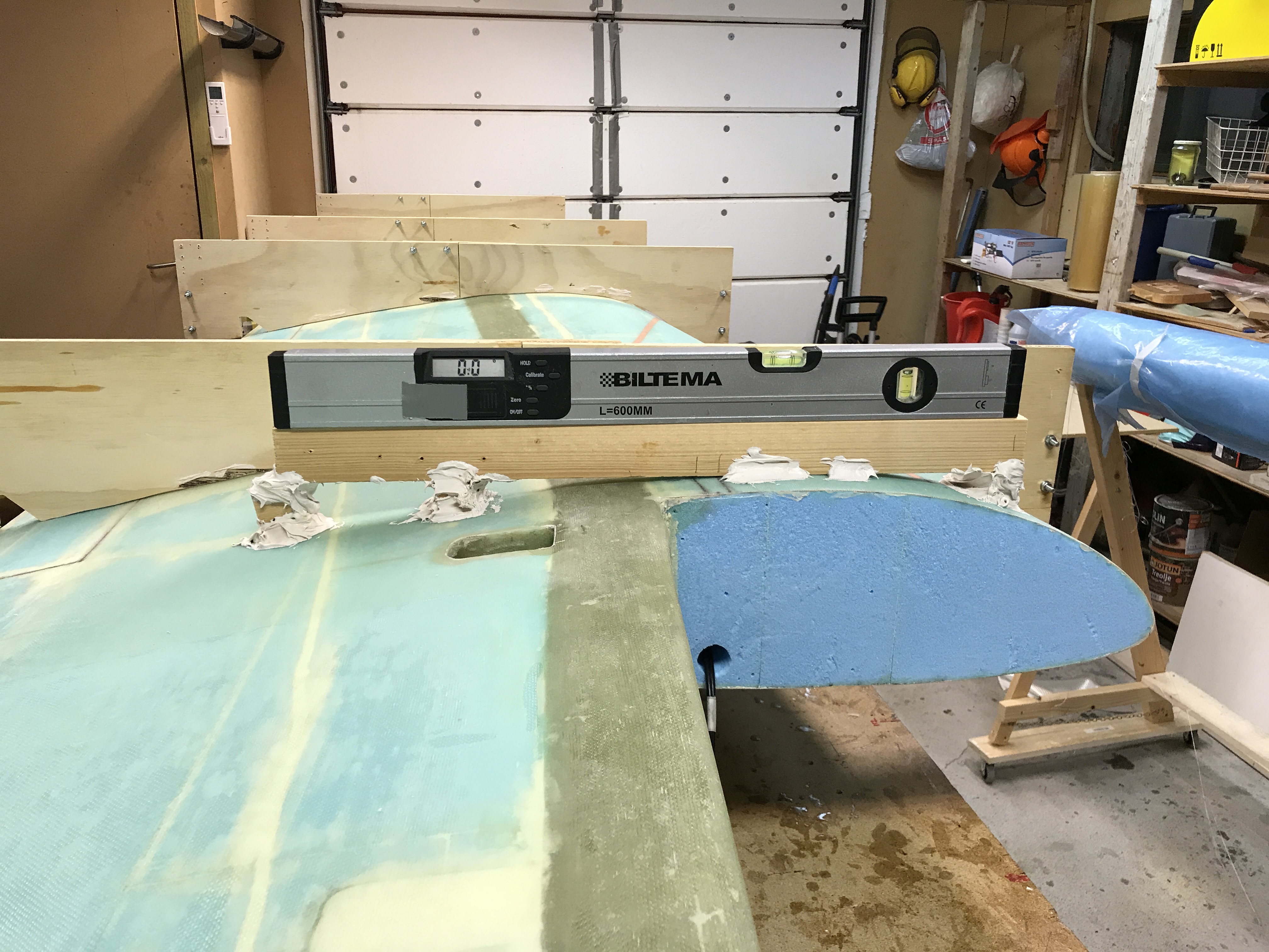
2019-03-12: Hindsight: Be aware that layup #5 in the next step (step 9) will come in conflict with the way I bondoed the reference wood piece. The marked area on the wing represents the UNI strips for layup #5. It comes in conflict with the blob of bondo.
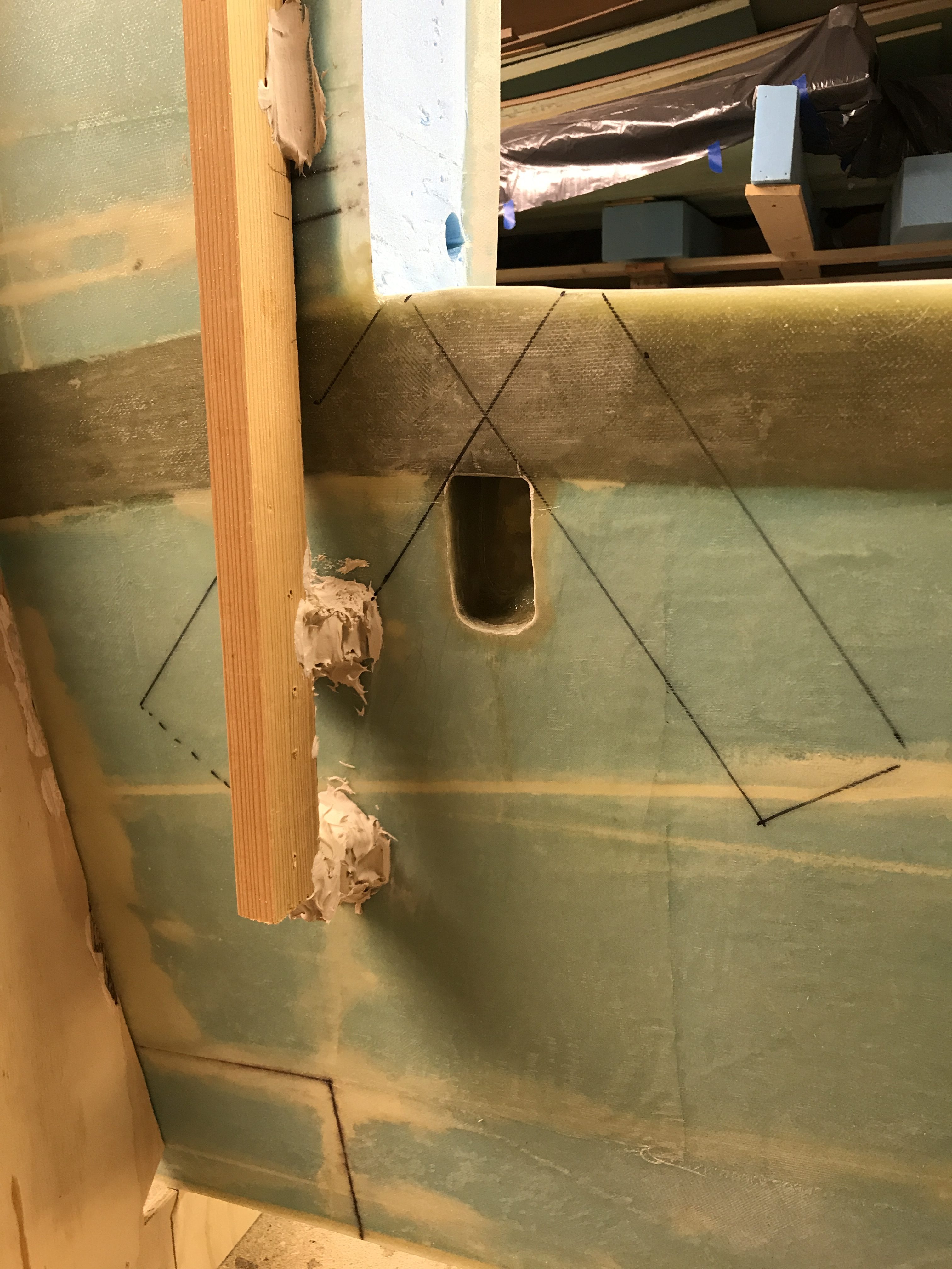
I had to remove the bondo to make room for the UNI. ANother 30 minutes of wasted time… 🙂 It should have been mentioned in the plans!
