This is the official start of the project!
I will make my first real parts, all the bulkheads, the front seatback and the firewall. It starts easy to give me some experience before things get more tricky. Not much to explain here, I will only post some pictures here.
Step 1: Front seatback

The front side is glassed with two plies of BID on the front side, and one ply on the backside.
Step 2: Forward bulkheads
A lot more work here. Combinations of BID and UNI makes these parts a bit more complicated. It’s important to take your time and read the instructions before you start up. I decided to cut all the glass for the side I was going to work with, and place them in sequence. That includes the peel-ply as well.
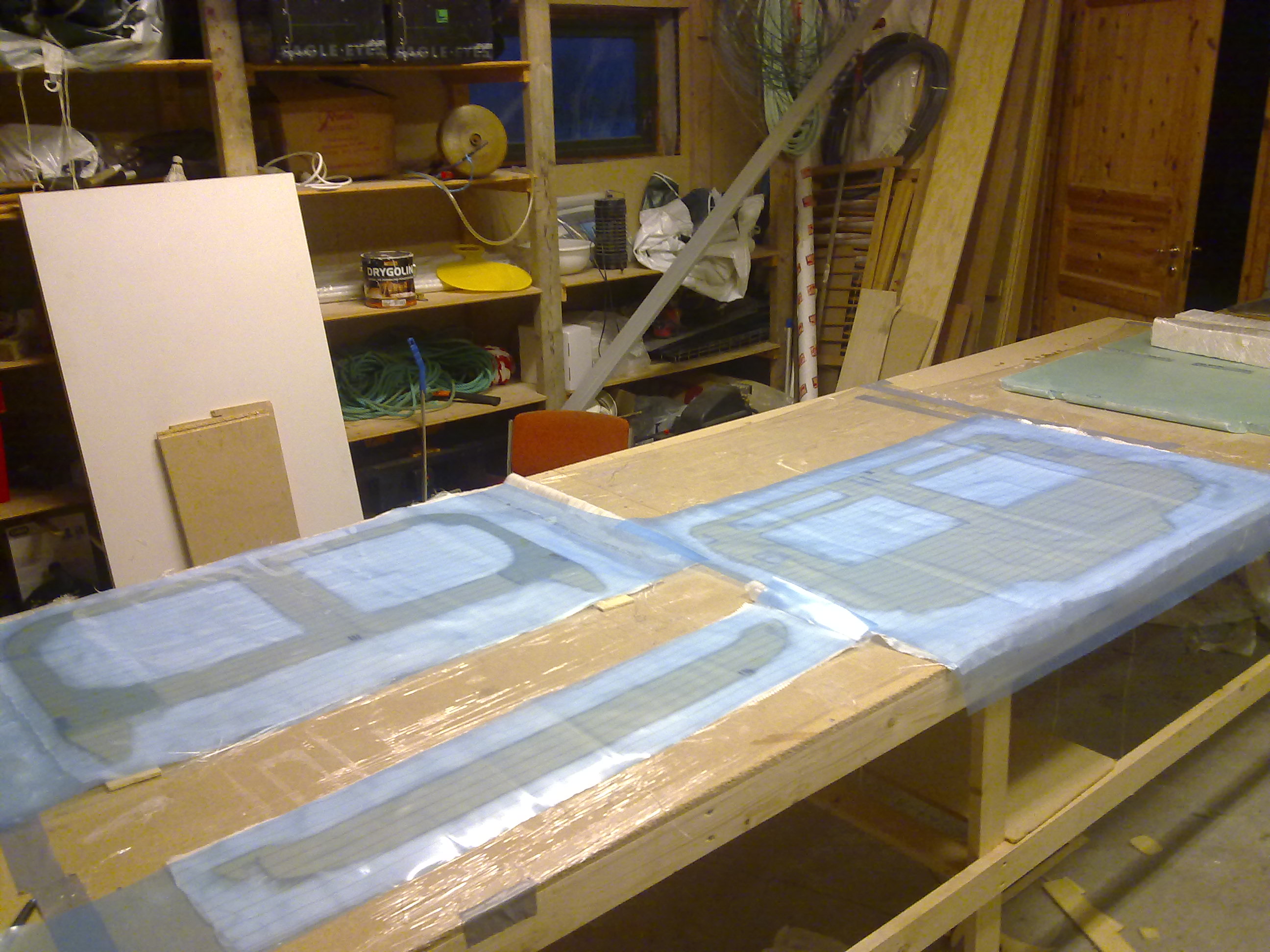
Here are the parts glassed, with peel-ply and a plastic-cover on top as a release-agent since I am going to weight down the parts.
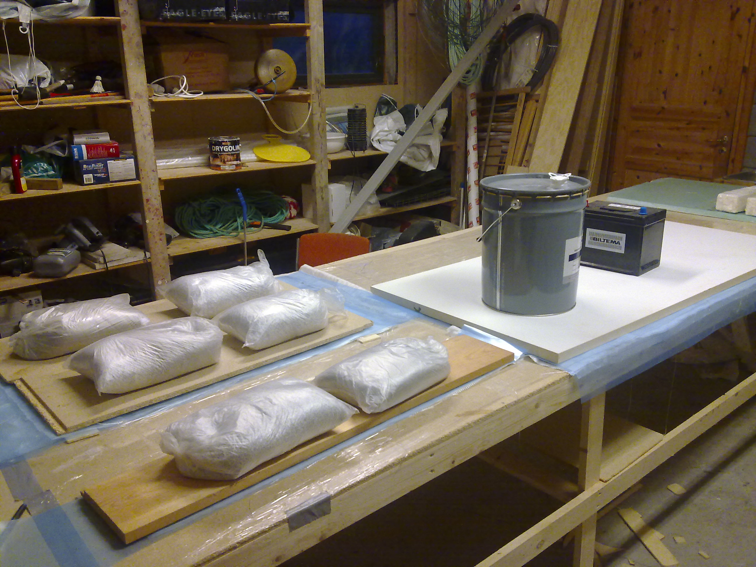
The parts all weighted down using sand-bags and some other heavy stuff.
Step 3: Instrument panel
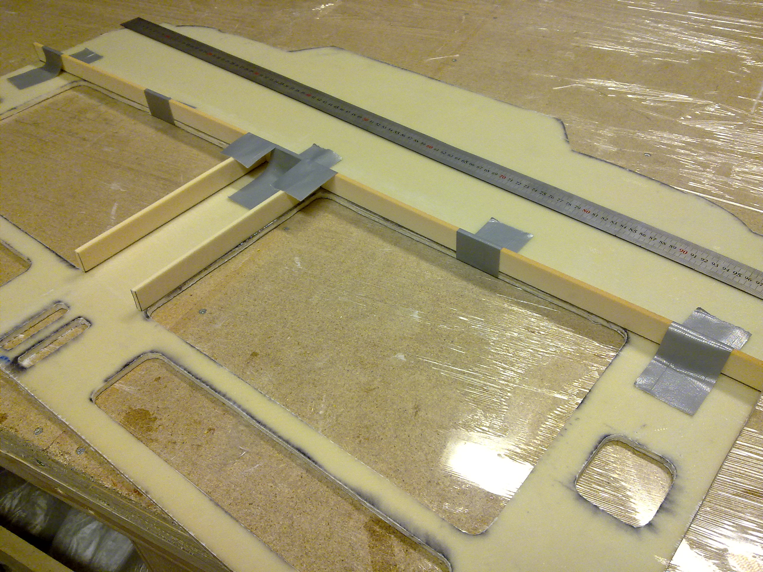
The instrument panel – IP for short and used hereafter – has some stiffeners attached on the front side. The drawings and pictures in the instructions are not very good at this point so I had to look through several builder-pages before I understood what I was going to do here. These ribs has two purposes: To stiffen the IP and act as cable-guides later on.
They are made of the same foam as the IP, 1″ wide/tall whatever… The first picture here shows the lower horizontal rib and the two vertical ribs. There is also an upper rib as you will se in the pictures further down. The ribs are simply glued to the IP using 5-minute epoxy. Remember to rub the IP with sandpaper prior to fastening the rib, to ensure proper surface for the glass that are to be epoxied later on.
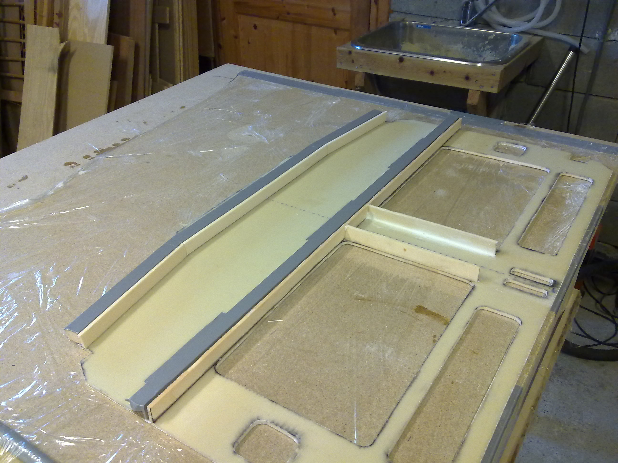
The ribs are then covered on one side first with one ply of BID then set to dry. The corners are to be filled with dry micro to make a find rounded corner for the glass to follow. You see this in the next picture – the white line between the IP and the vertical rib. After cure and trimming the fun part begins. Now we are to make a cabel-channel out of the ribs! It took me some time to understand this, but again – thanks to all the builder-pages I figured this out. The channel is made of two plies of BID wrapped over the rib and onto a temporary support I made of some 1″ thick wood I cut on my saw. I covered the wood with duct-tape to avoid the glass to fasten to the wood. Then I glassed the other side of the rib, bending the glass over the temporary supports I made. I covered it all with peel-ply and set to dry.
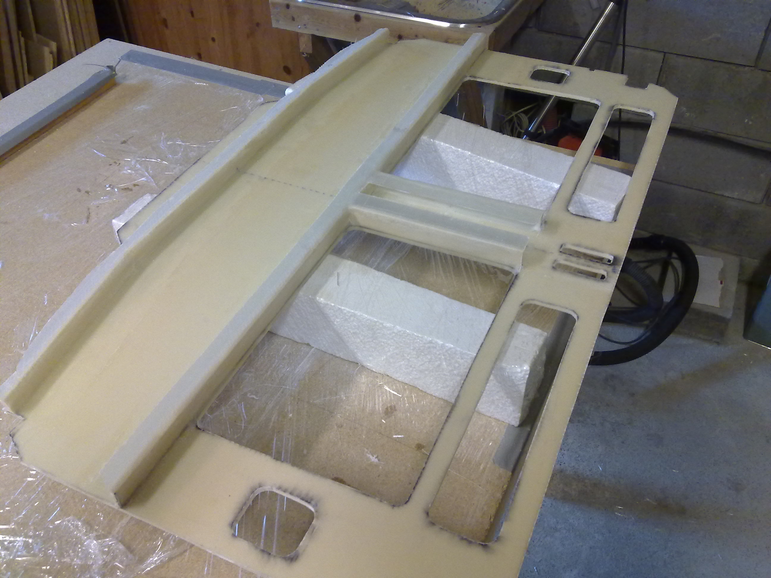
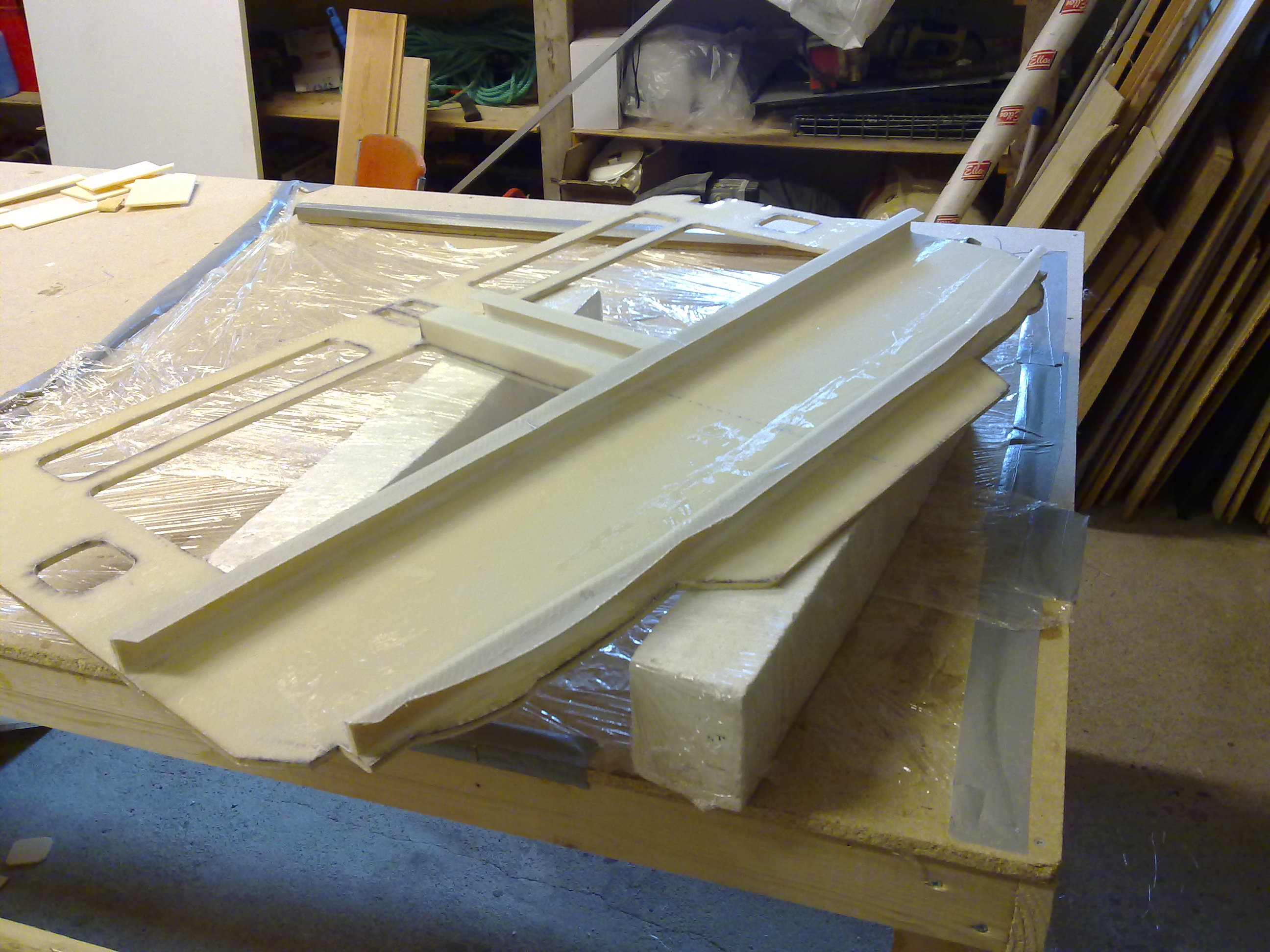
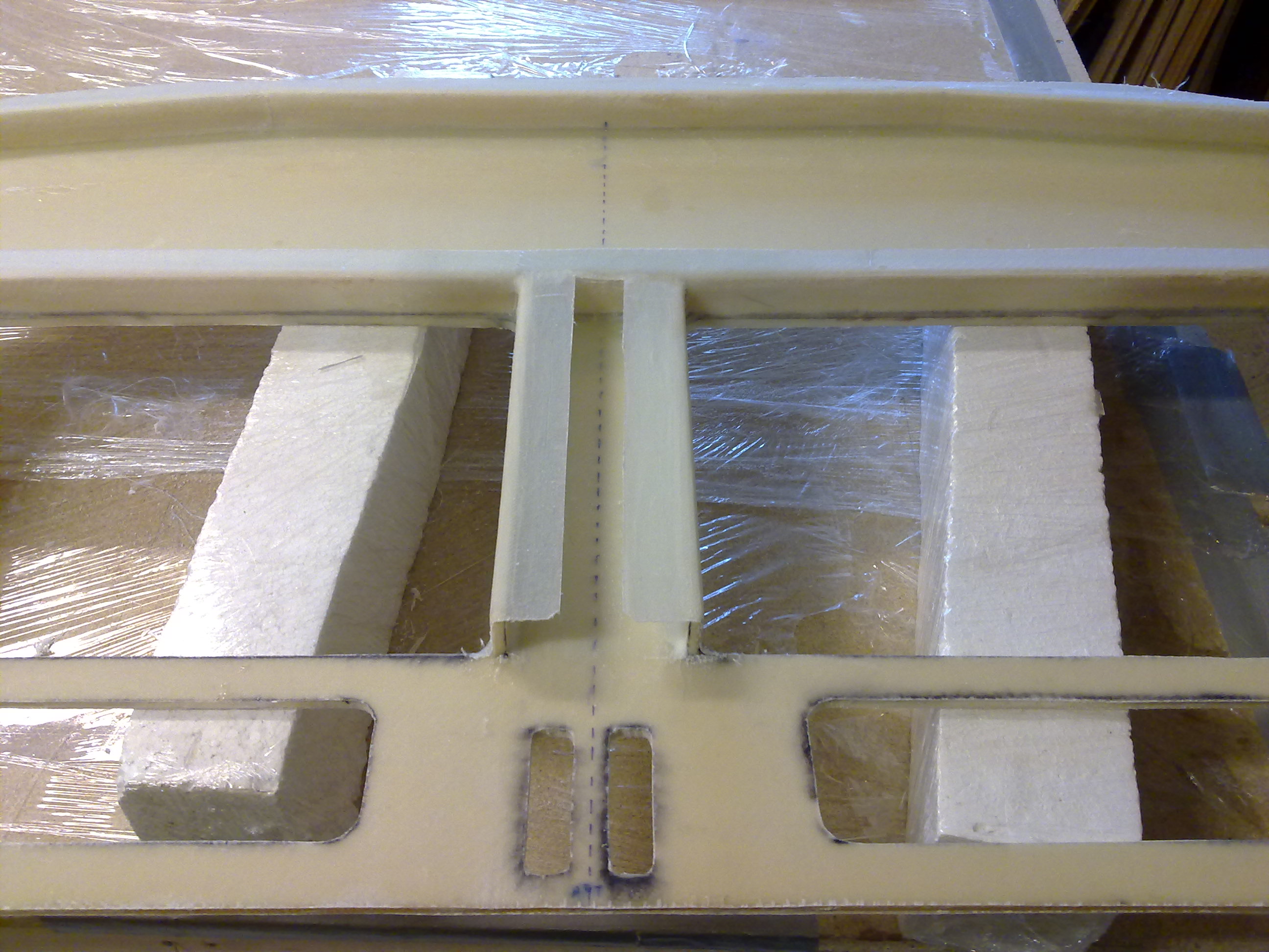
After cure I carefully removed the wood-supports and trimmed the channels. Turned out to be rather good I think.
Step 4: Landing Gear Bulkheads
Not much to say other than “follow the plans”. I did one mistake resulting in that I had to remake the upper bulkhead. The problem was that the hardener-tube on my epoxy-dispenser had clogged with crystalized hardener. This resulted in less hardener in the epoxy and a part that did not cure properly. Lesson learned. The remake didn’t take much time or effort. Making the hardpoints resulted in them beeing approx 1,5mm thicker then the foam. Using a belt-sander I reduced the 1,5mm of glass to a whole lot of dust.
Step 5: Firewall
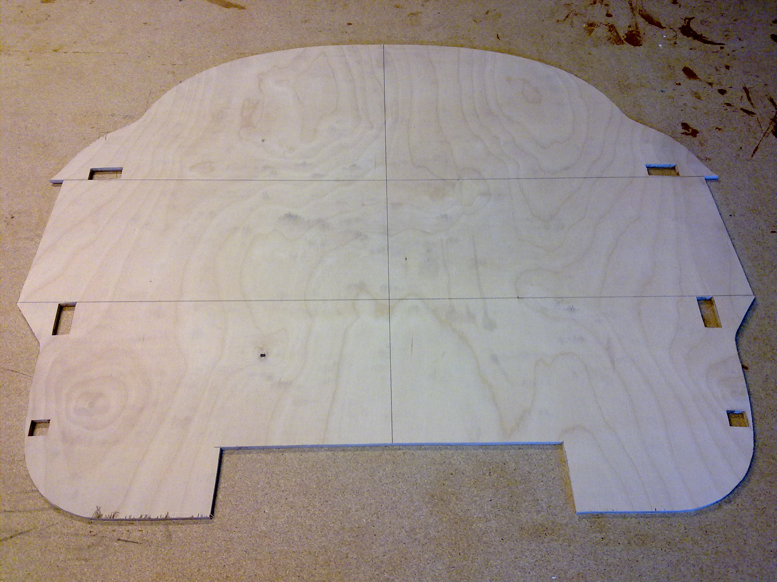
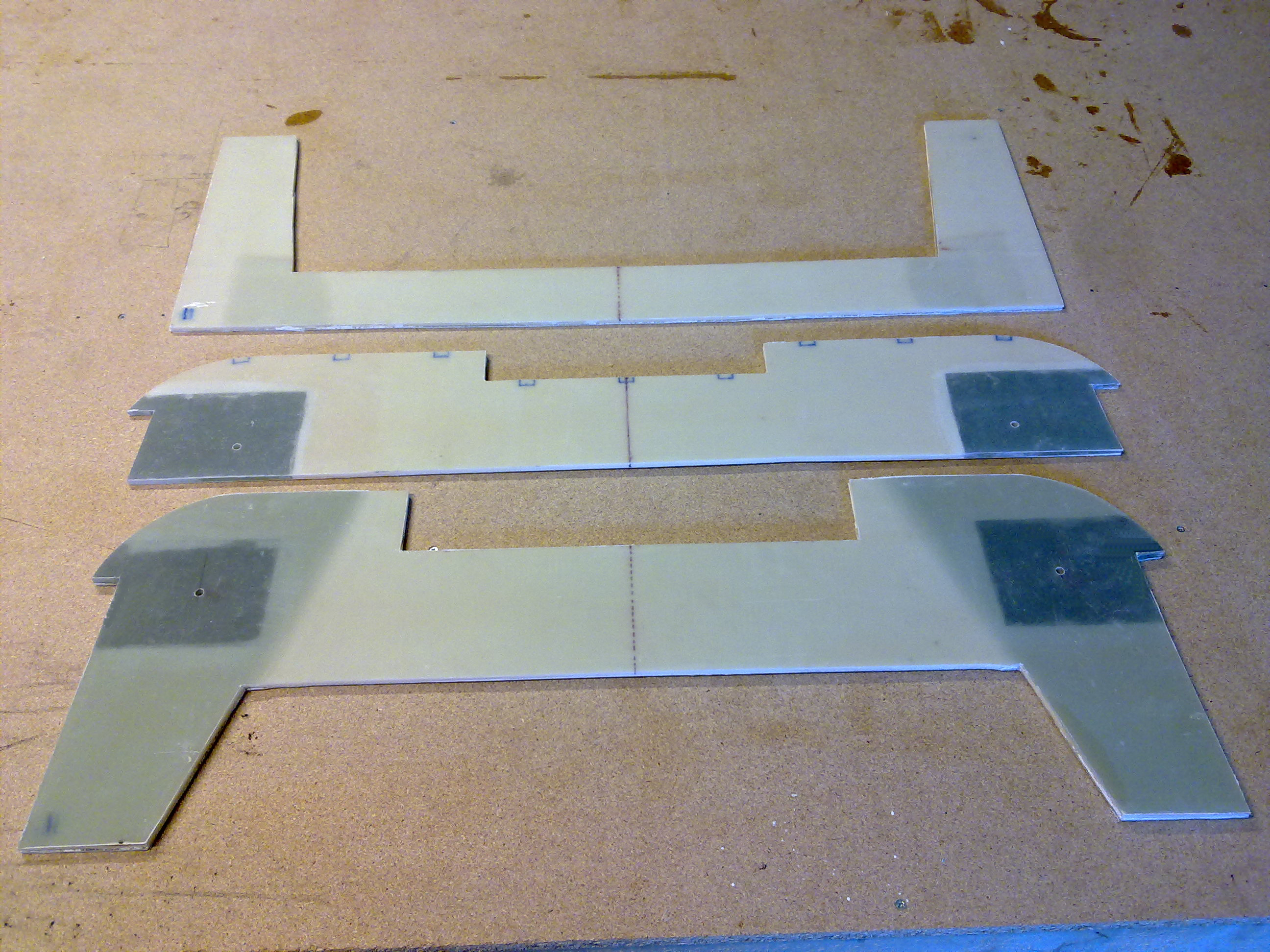
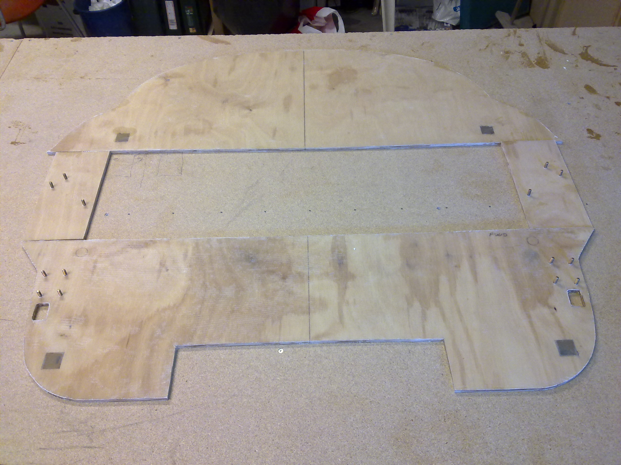
The firewall consists of two parts, a temporary firewall to be used as a template and a help when mounting the tub together later on, and the permanent firewall broken down in four pieces. I traced the drawing onto a paper and cut out all the parts from 6mm birch-plywood. The temporary firewall is then left as it is, with some cut-outs for the longerons only. These will later be adjusted and transfered over to the permanent firewall.
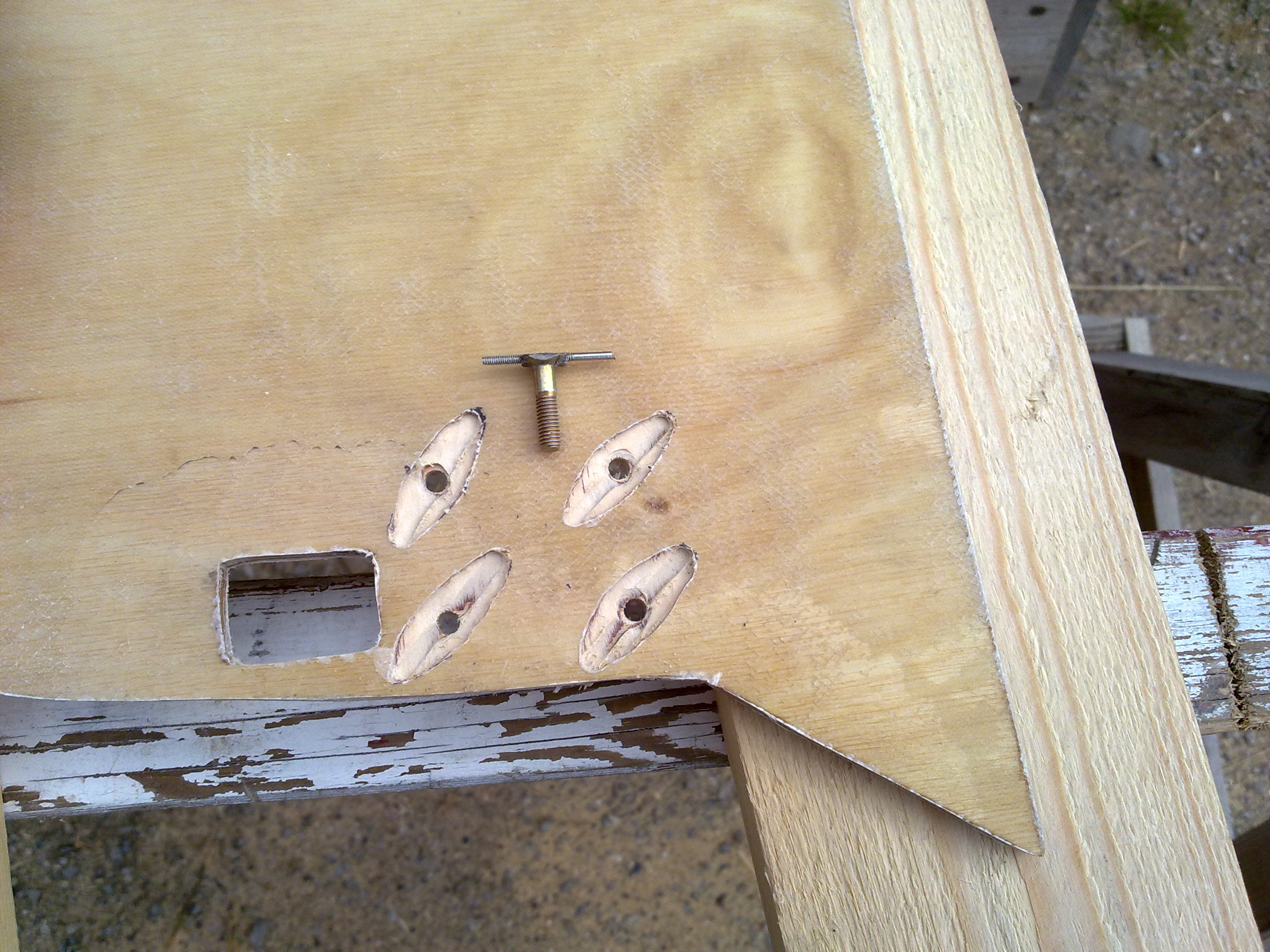
The permanent firewall consists of four separate parts made of plywood. They are to be glassed with one ply of bid on each side. In addition to this four aluminum-inserts are to be mounted as well as 14 screws.
The aluminum-inserts have to be treated to prevent corrosion. The recommended way is by using a chemical called “Alodine”. The first step is to clean the parts. I was initially going to use a chemical called “Alumiprep” but is was not possible to get this in Norway. Shipping it from US was not possible either since it’s considered as haz-mat. After some research I was told that I could use Hydrochloric acid instead (Saltsyre in Norwegian), which I could buy in my local hardware-store. So the parts were treated with acid, rinsed in water, then treated with Alodine, then rinsed in water again and dried before they were mounted in the firewall. The hole was so tight that I didn’t have to flox or glue them in place at all.
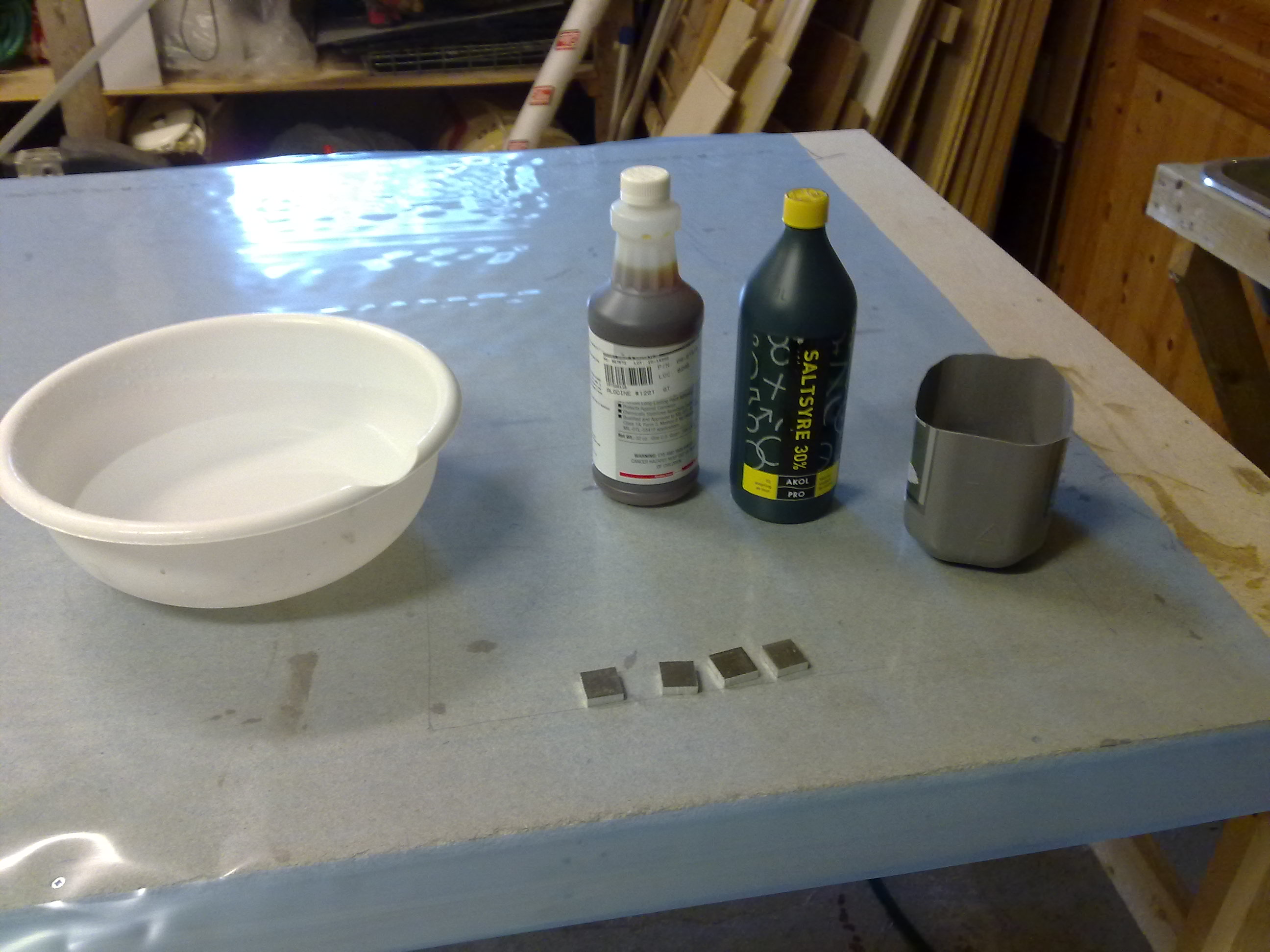
Ready for the process.
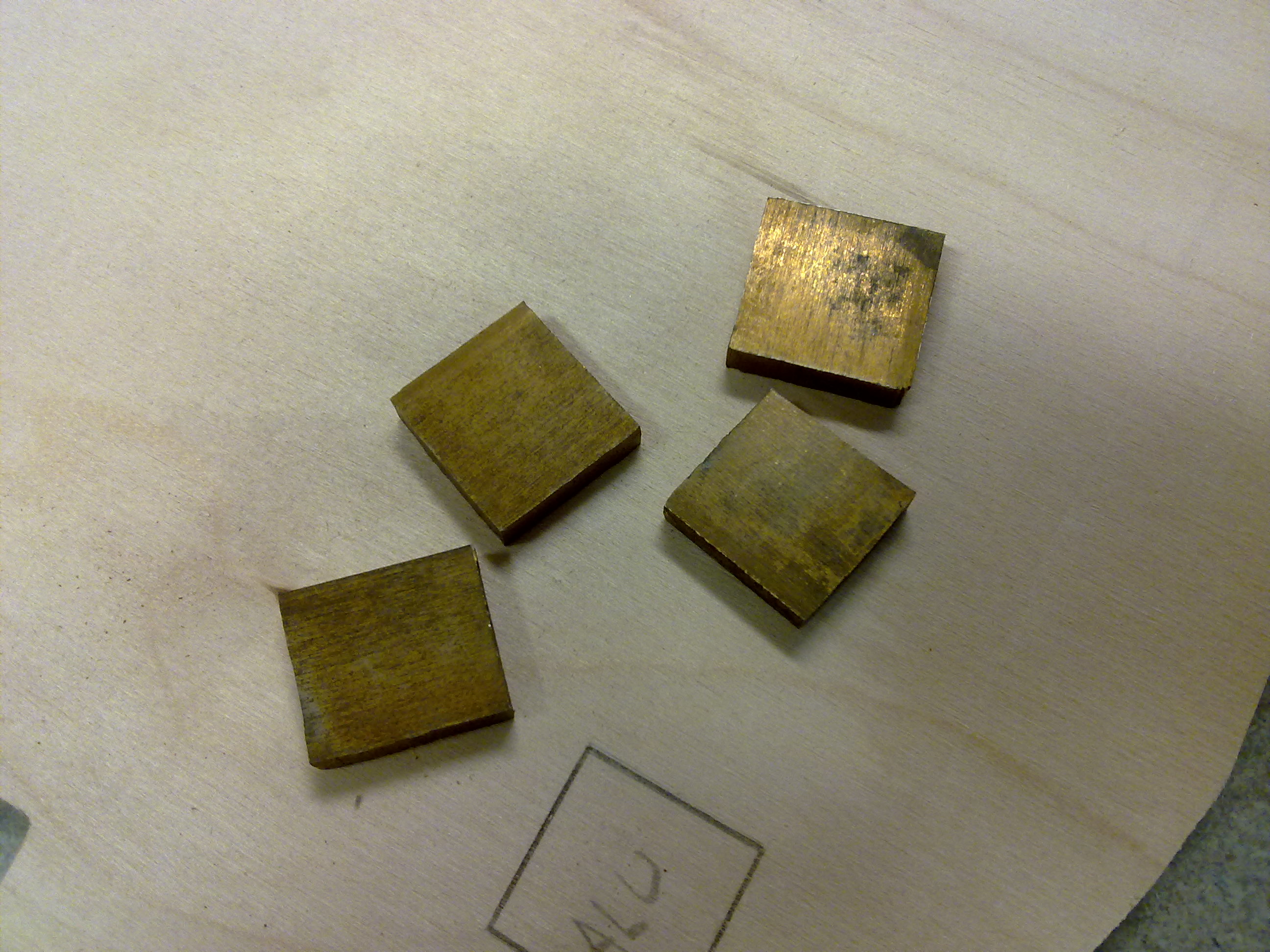
And here are the parts Alodined. They get a yellow/golden tint.
The screws to be mounted has a history of coming loose making it impossible to fasten the nut on them. This is because the head is hidden in the firewall behind layers of glass. To prevent this it was adviced to make a notch in the head to get the flox to “bite” properly. Other has instead welded a piece of music-wire on the head making it more difficult to rotate. I chose to follow that part. One exception – I didn’t have access to welding-equipment so I used some very strong epoxy-glue for gluing metal. Turned out to be very good. Here are some pictures of the process:
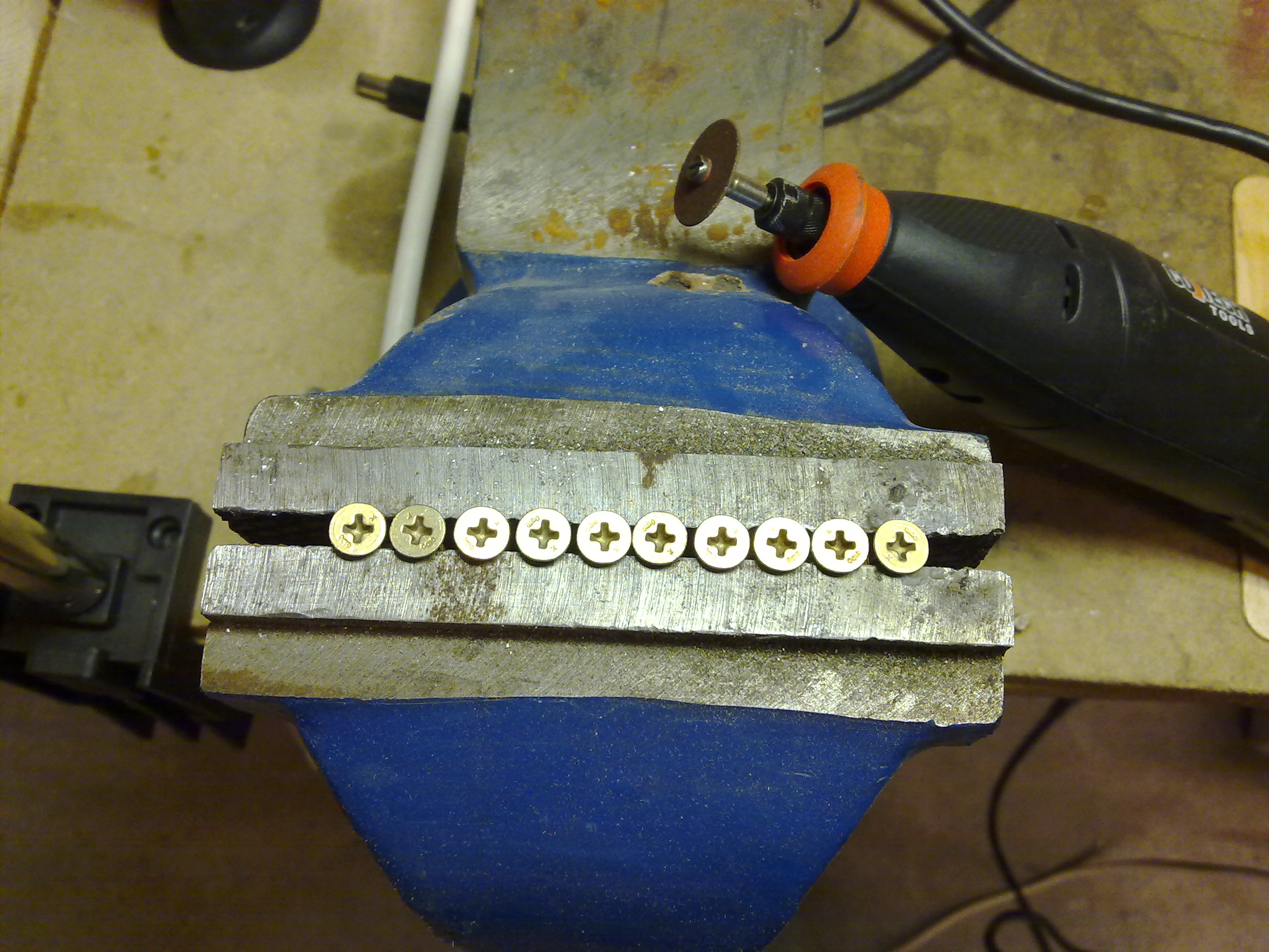
I started by fastening the screws in a vice.
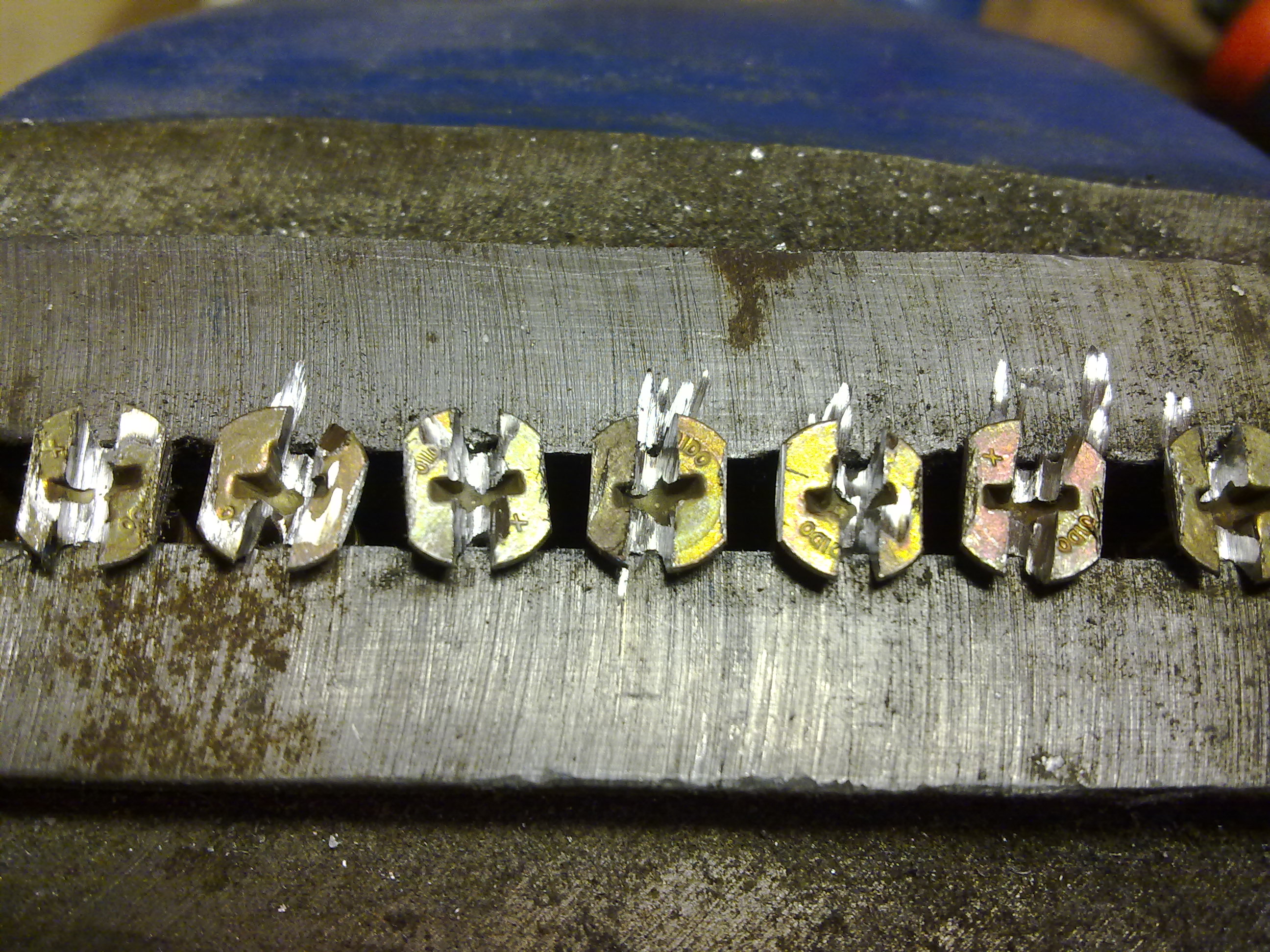
Then I cut a slot in the head to make room for the music-wire. I also grinded the head flat on both sides to make it even more stable.
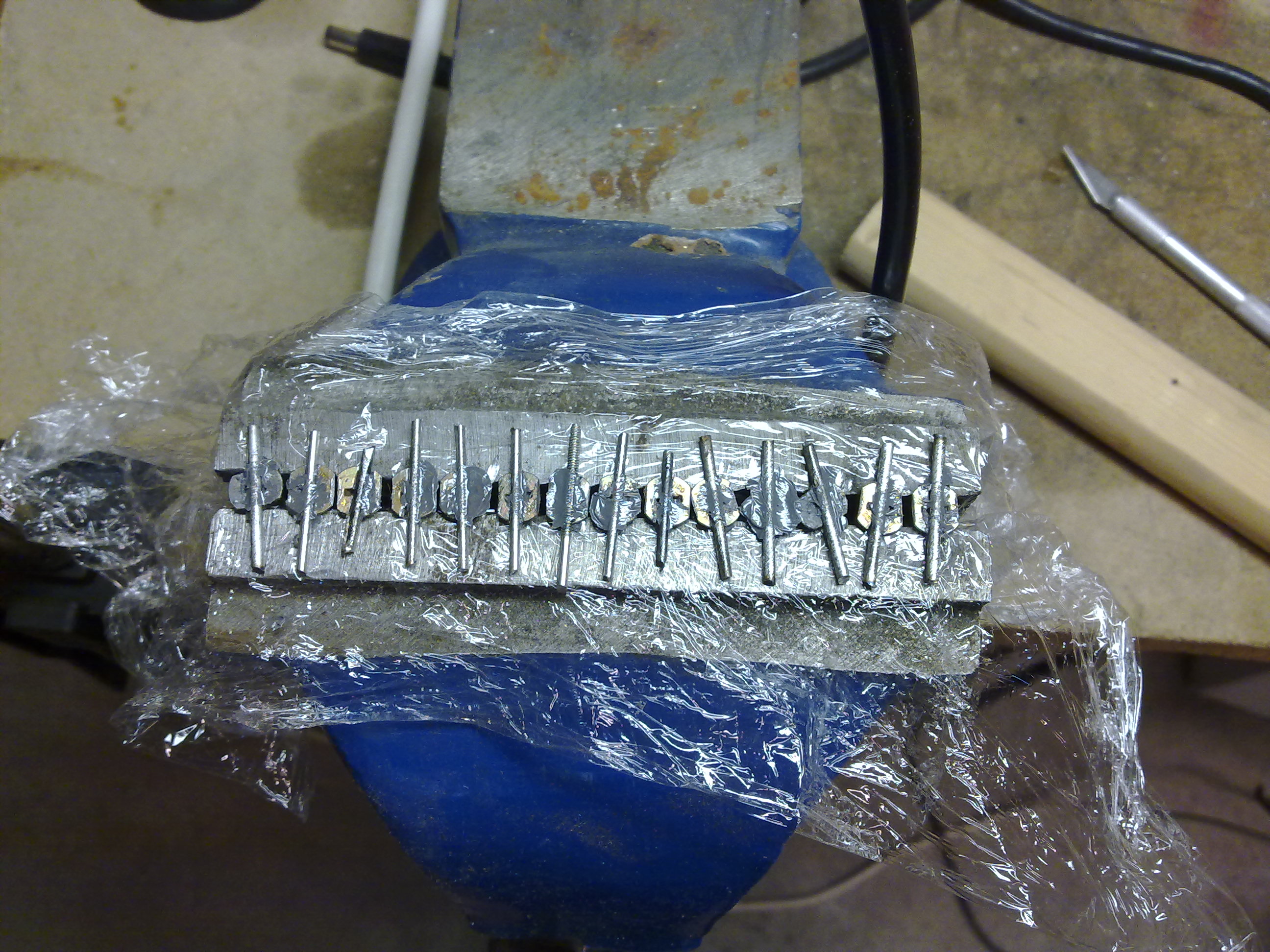
Here the music-wire is epoxied to the screws.
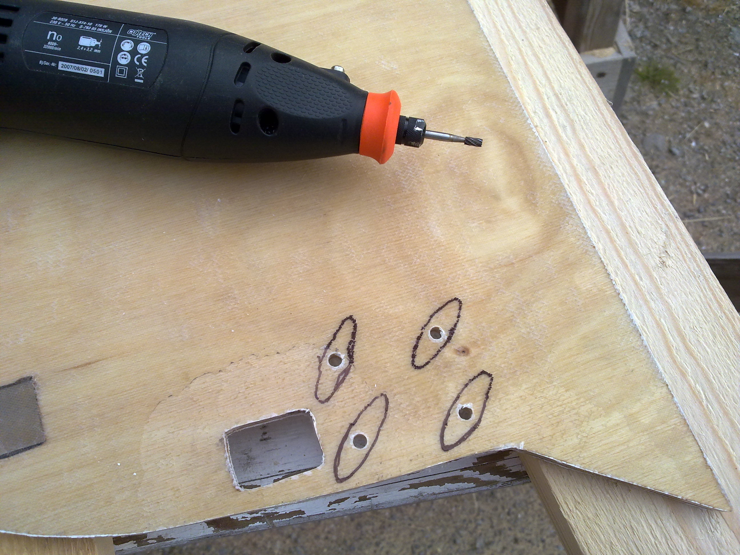
I then used the Dremel to route space for the screws.
Ready for floxing.

Here the screws are floxed in place and covered with BID.
The permanent firewall finished so far.
And that was the end of this chapter. The parts came out pretty ok I believe. I have weighed them and compared to other builders and they are normal in weight as far as I can see. Here are my figures:
| Part | Weight (grams) |
| Front seatback | 2500 |
| F22 | 1043 |
| F28 | 305 |
| Instrument-panel | 1934 |
| Landing gear fwd upper | 397 |
| Landing gear fwd lower | 625 |
| Landing gear aft | 1203 |
| Firewall upper | 1408 |
| Firewall middle | 250 |
| Firewall lower | 1205 |
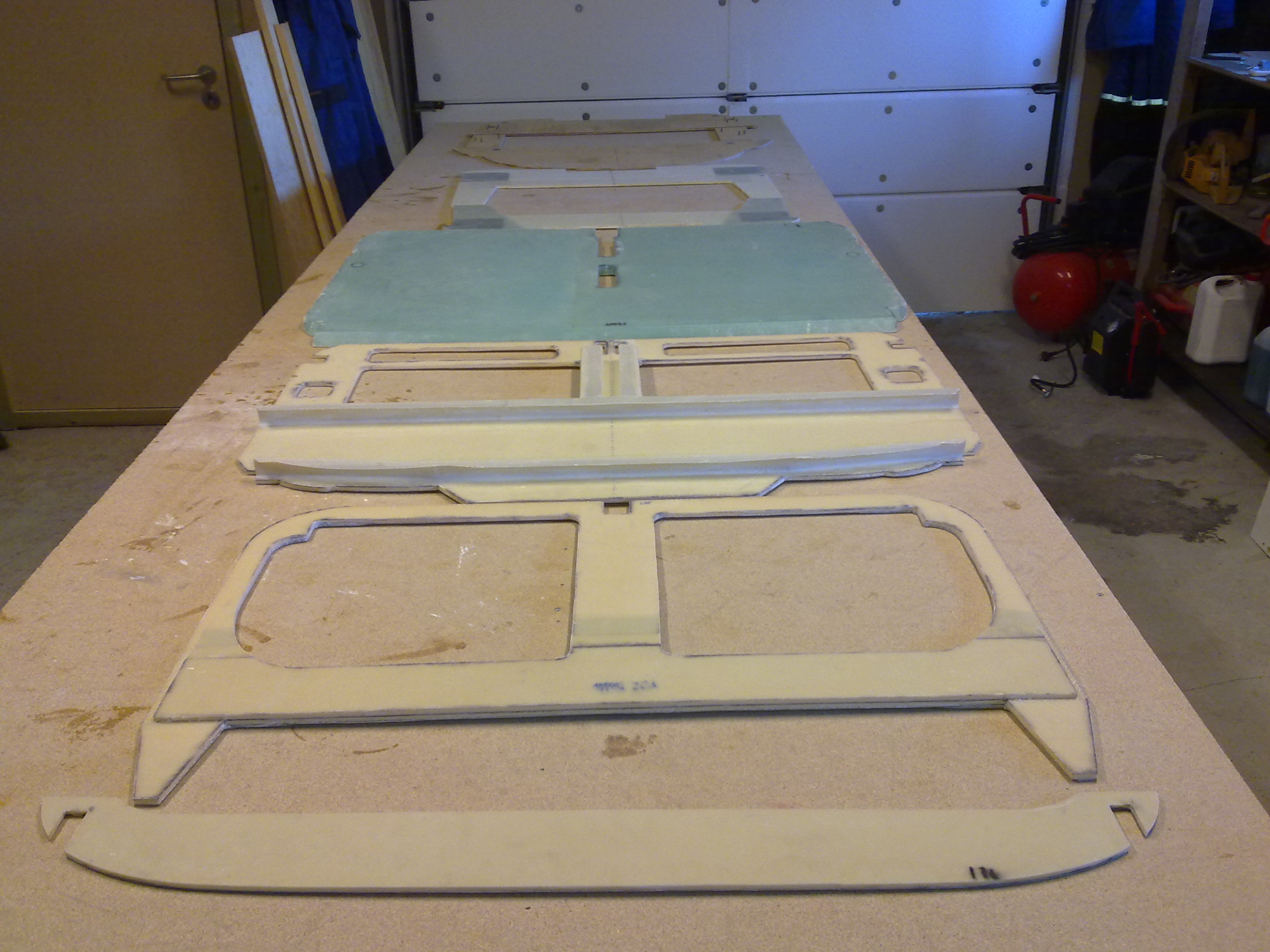
Here are all the parts lined up.

Here I am using my Bosch Multicutter to trim down the glass on the landing-gear bulkhead. This tool is amazing. I never knife-trim any parts, instead I use this tool or my Bosch jigsaw. I love my power-tools 🙂
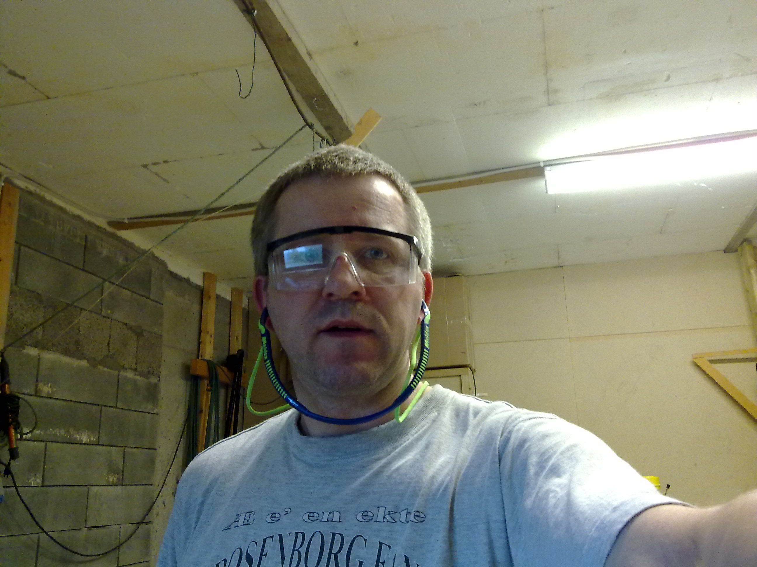
When I use these tools I wear both ear- and eye-protection. The noise-level are not healthy, so a lightweight ear-plug is mandatory. Also when cutting glass I won’t risk any needles in my eyes, glasses is therefore also mandatory for me!
Time used this chapter: 42:00 hours
Started: 2009-04-22
Ended: 2009-07-07
thank you your site is very inspiring and I m dreaming to build a cozy myself . Now looking for materials but as you know , are not easy to find in Italy… so one day will start . Regards ciao , Massimo