
In this step I will fabricate the NG-30 nose box. The plans says that this step should take only 5 hours, not counting the cure-time. I used 12,5 hours and I do not consider myself a particularily slow worker. How it’s possible for ONE man to do all this in 5 hours is more than I can understand…
I don’t rush anyway, I use the time it takes and enjoys the building process!
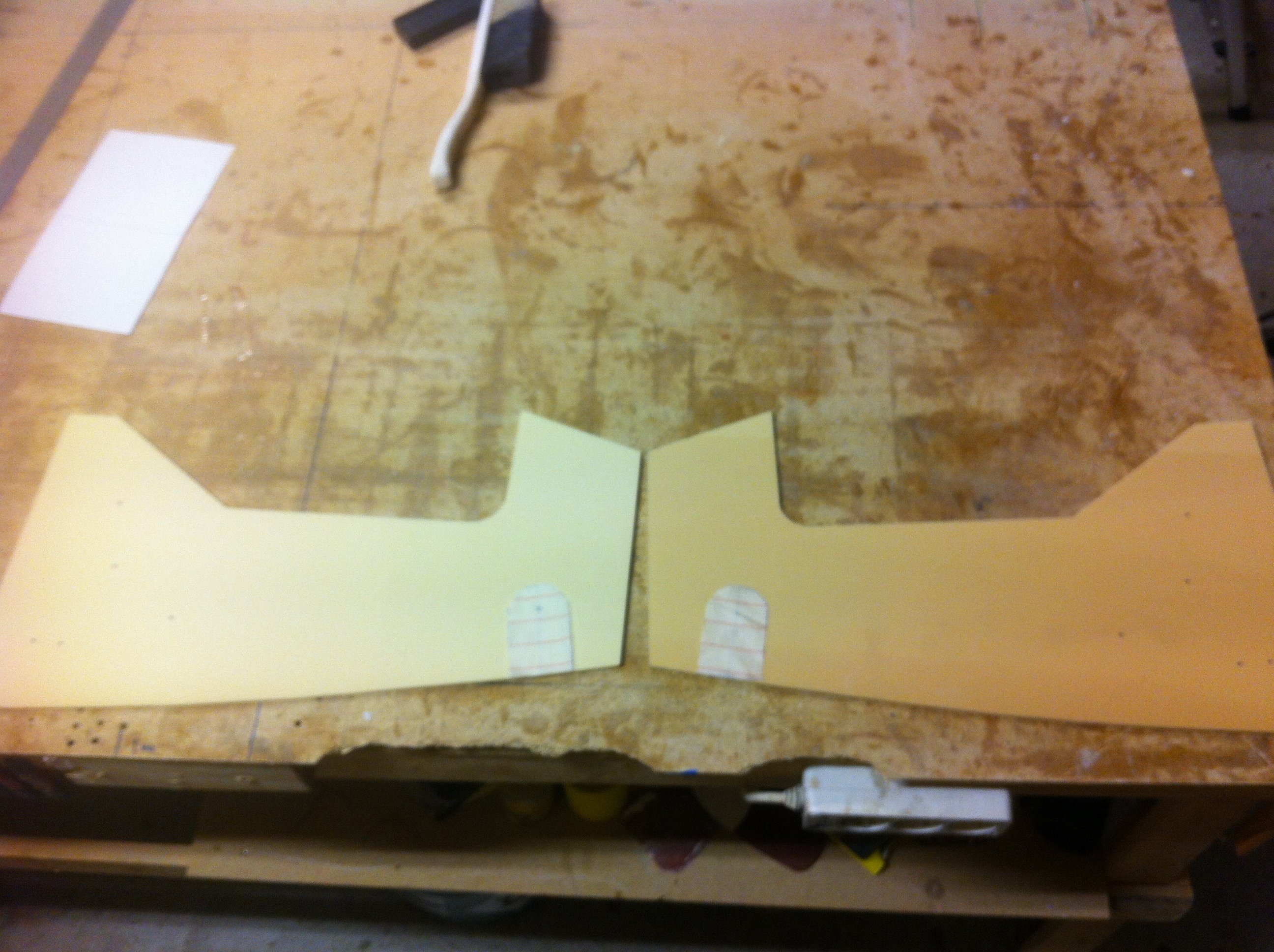
2013-04-5: I made a paper-template of NG-30, including the extra 2″ height in the middle as specified in the newsletter and the FAQ.
First I made the layup on the outside of NG-30 where MKNG6A is beeing mounted.
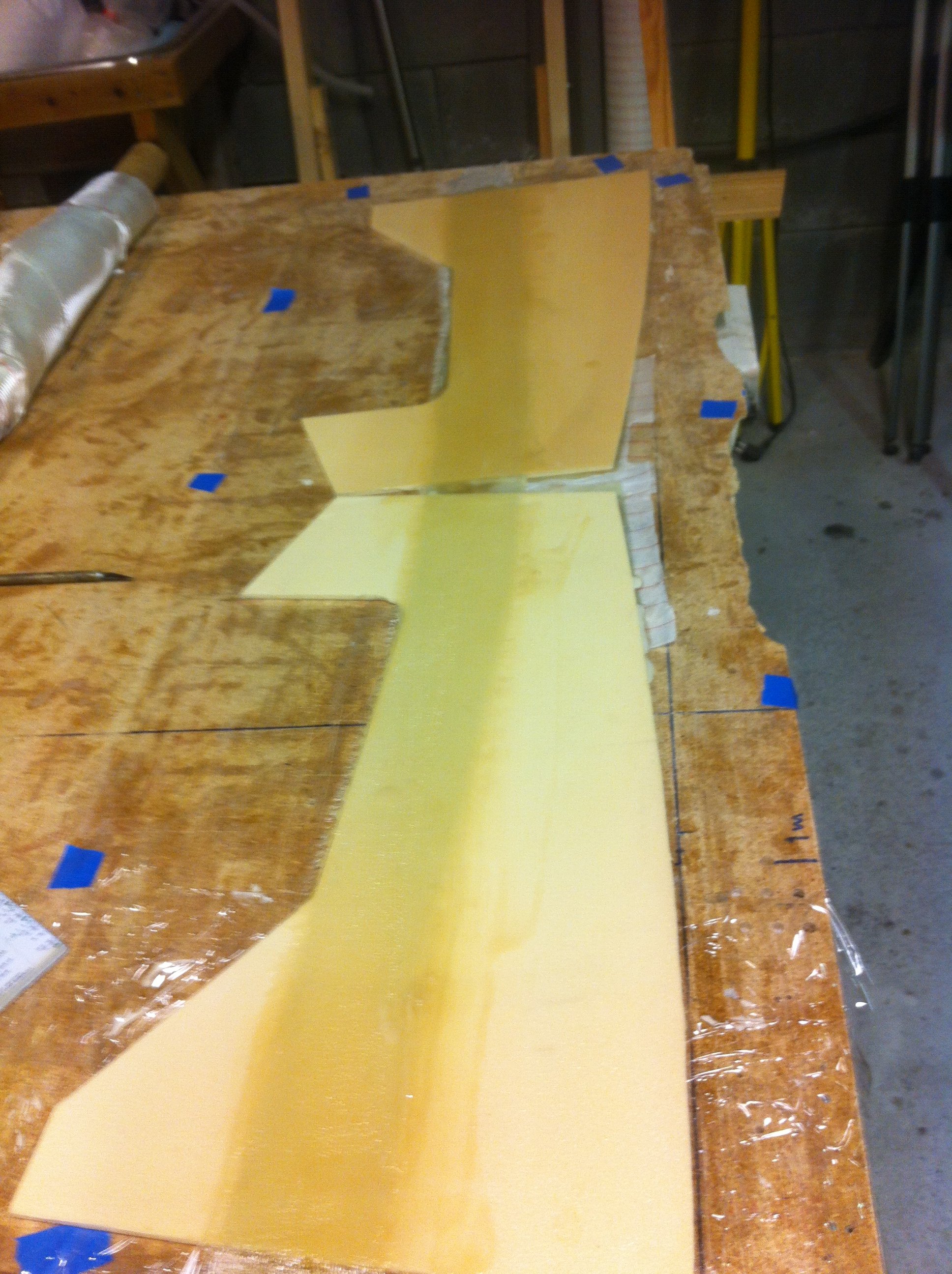
2013-04-5: Then I turned the whole ting upside down and covered the inside with 2 plies of UNI over the extra 2″, then 4 plies of BID.
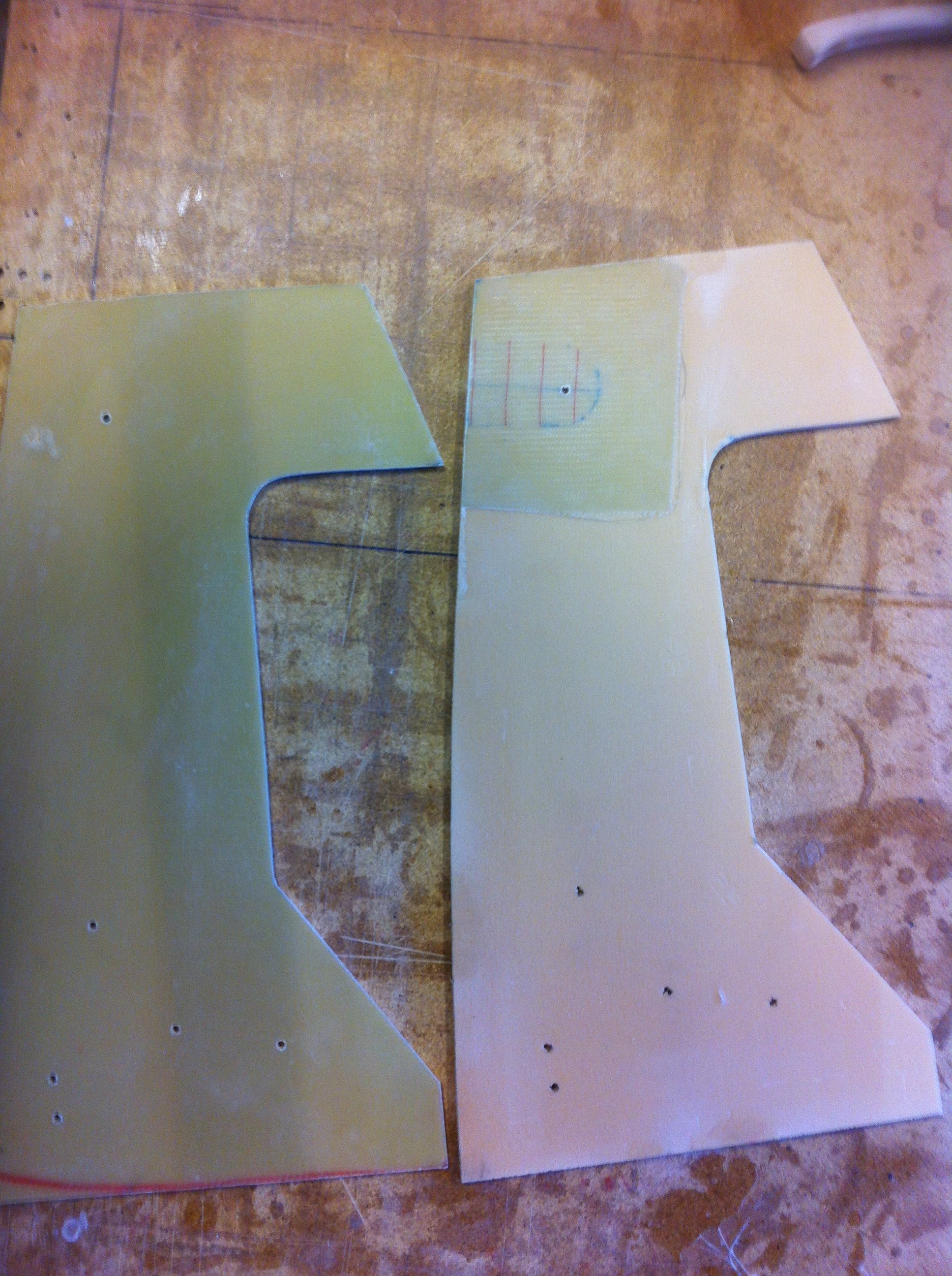
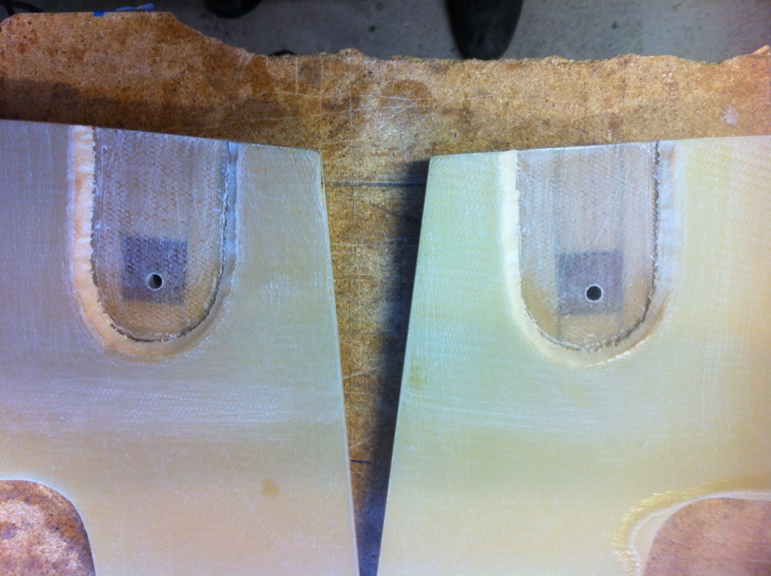
2013-04-6: The two parts have the edges sanded, and I drilled pilot-holes for the actuator, for the MKNG6 and for the rudder-pedals.
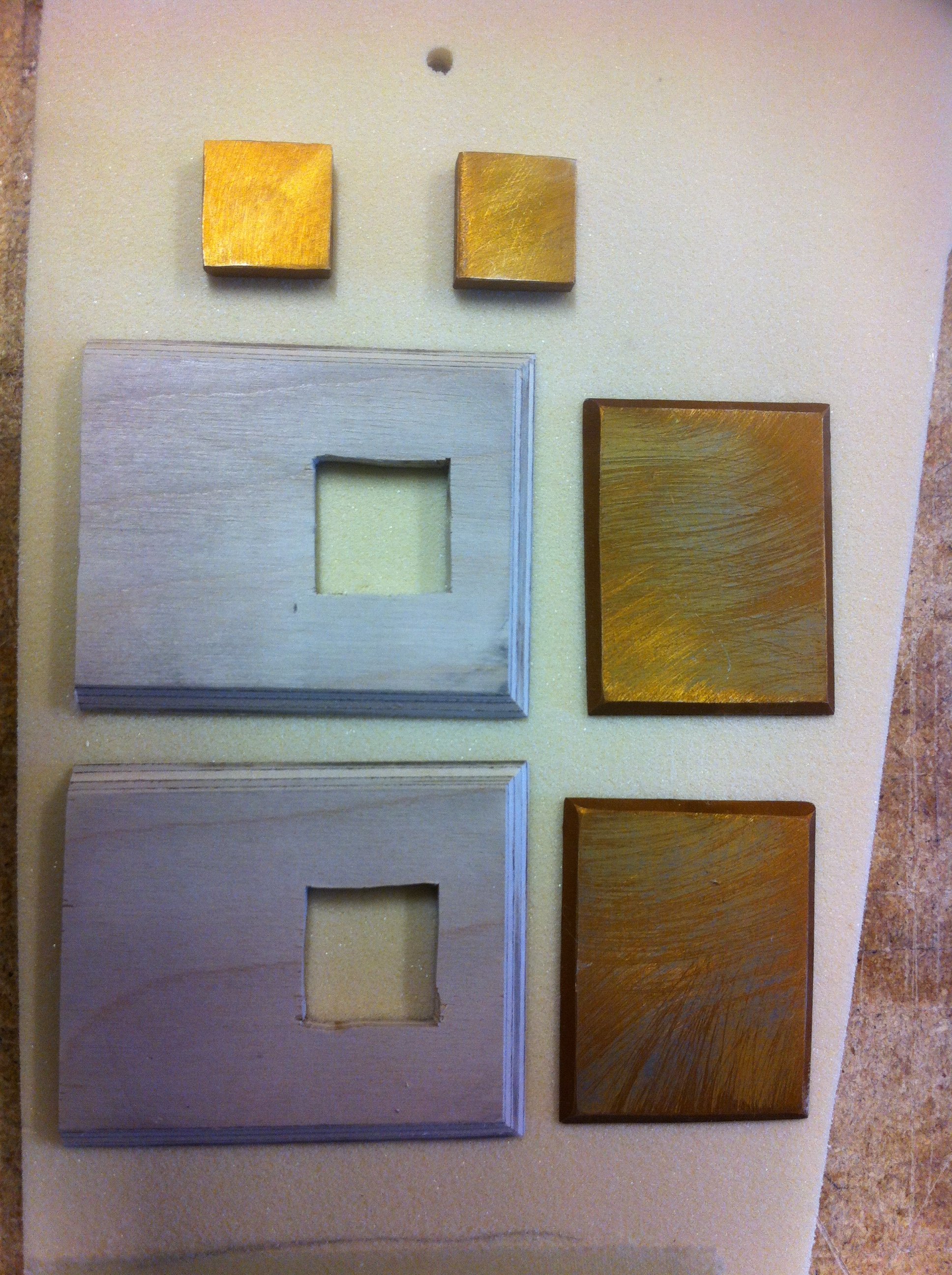
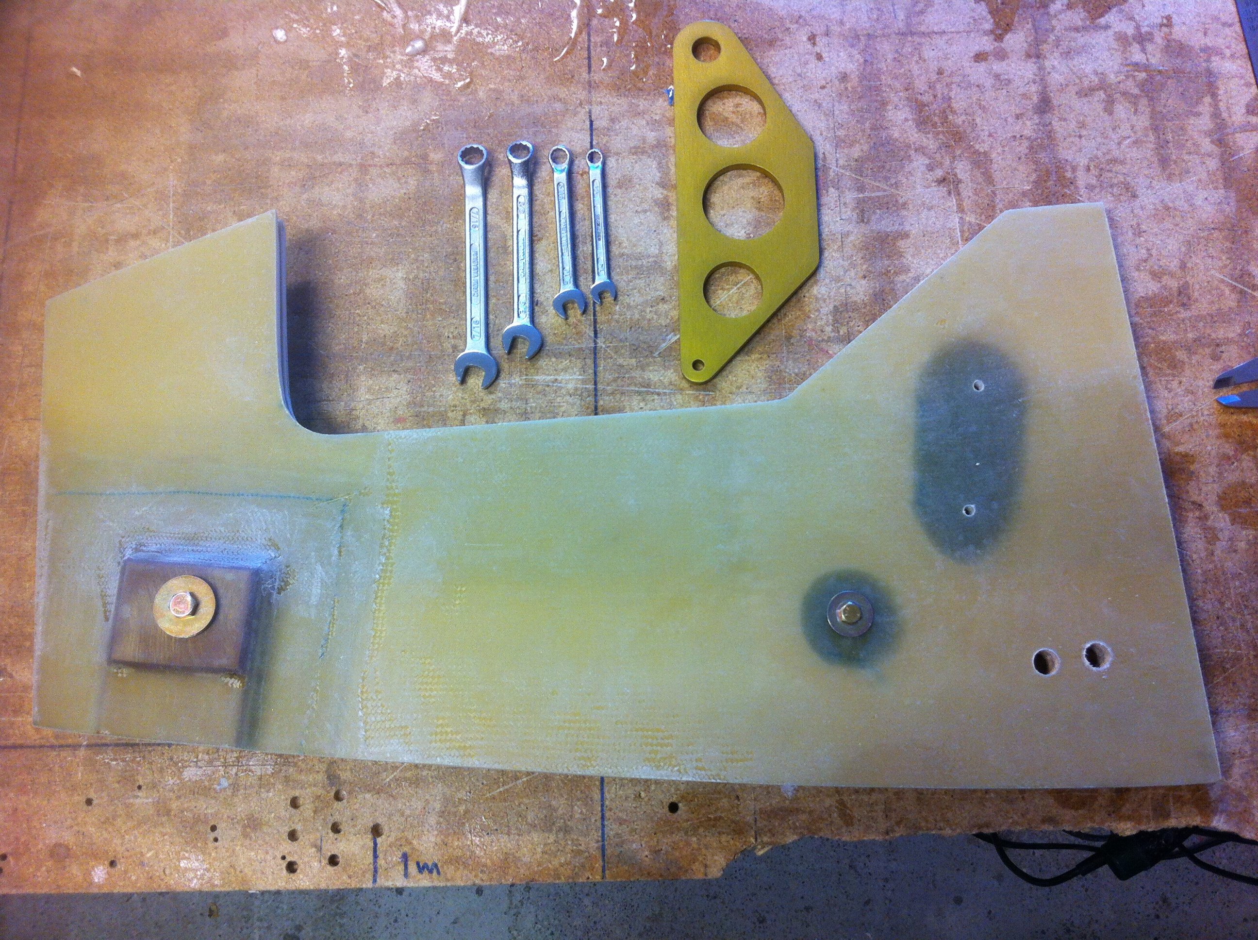
2013-04-6: Around the MKNG6 pivot-assembly there are a buildup of plywood and aluminum-doublers as well as some extra plies of BID. The aluminum is treatened with Alodine.

2013-04-6: The foam are removed around the mounting holes for the actuator, to make room for hard-point buildups of several plies of BID.
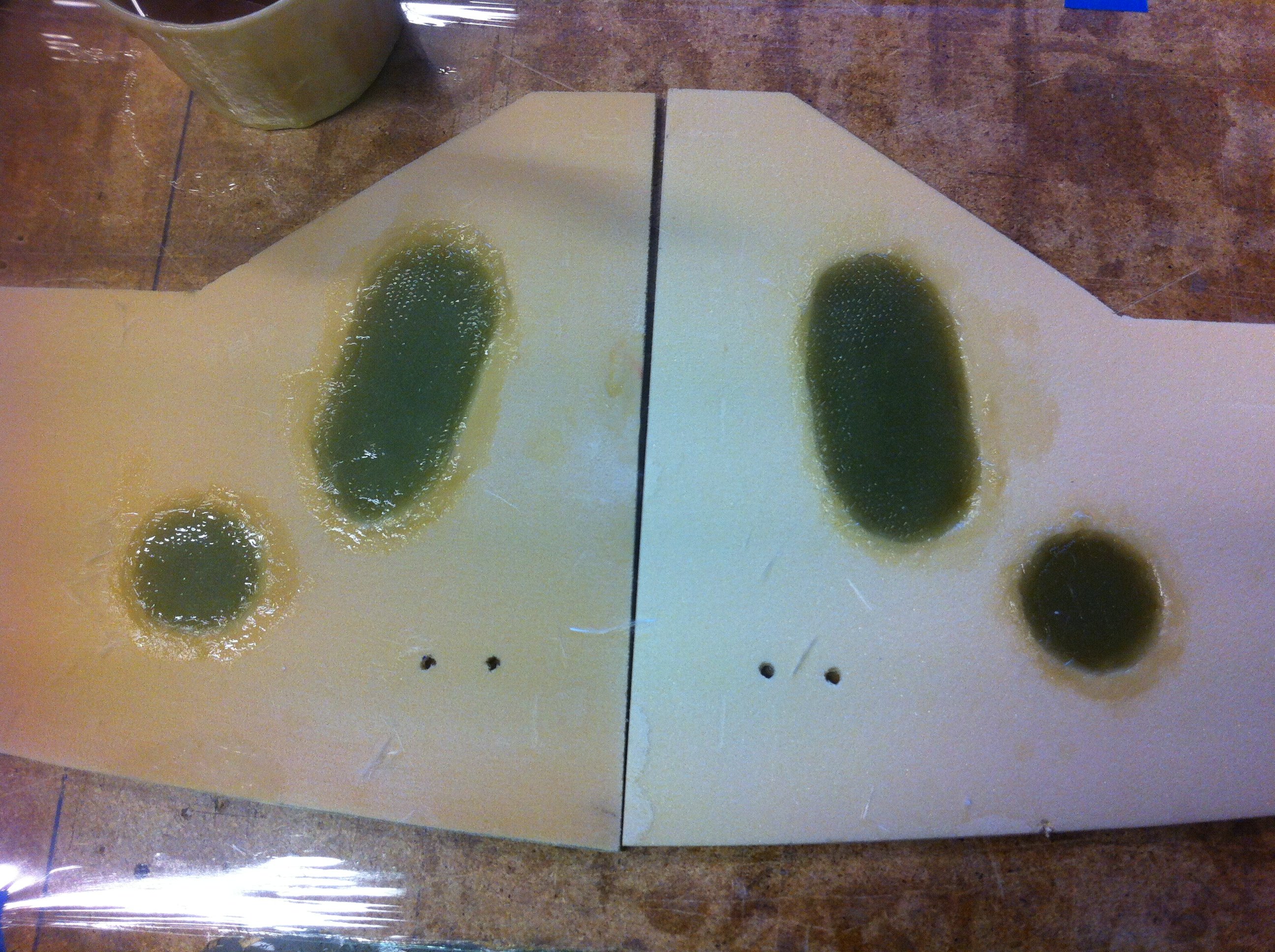
2013-04-6: I eventually ended up with 18 plies instead of the 15 that the plans says.
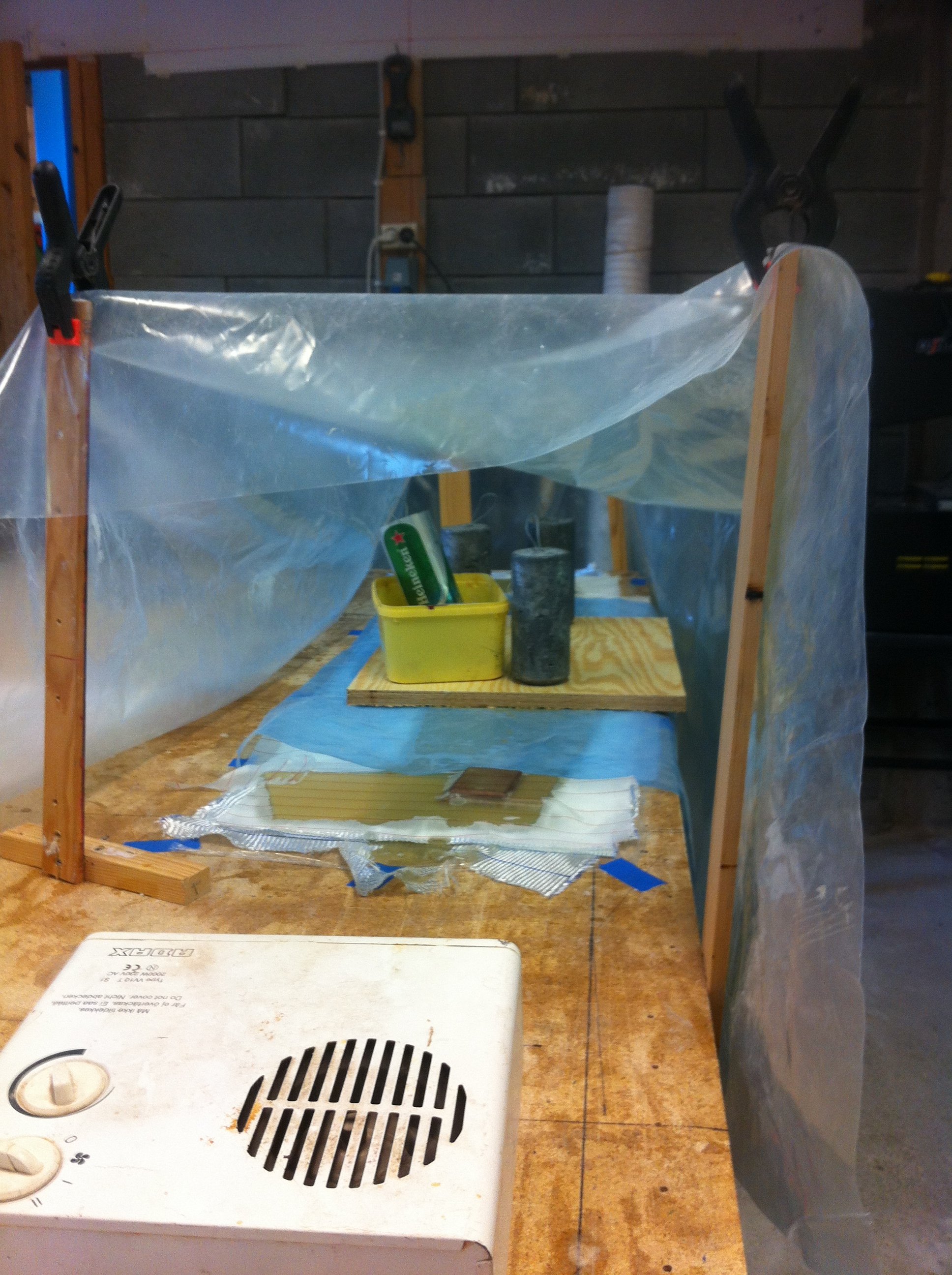
2013-04-6: The outside is peel-plied and the hardpoints are weighed down to ensure they are absolutely flat. Everything is curing in a heat-tent.
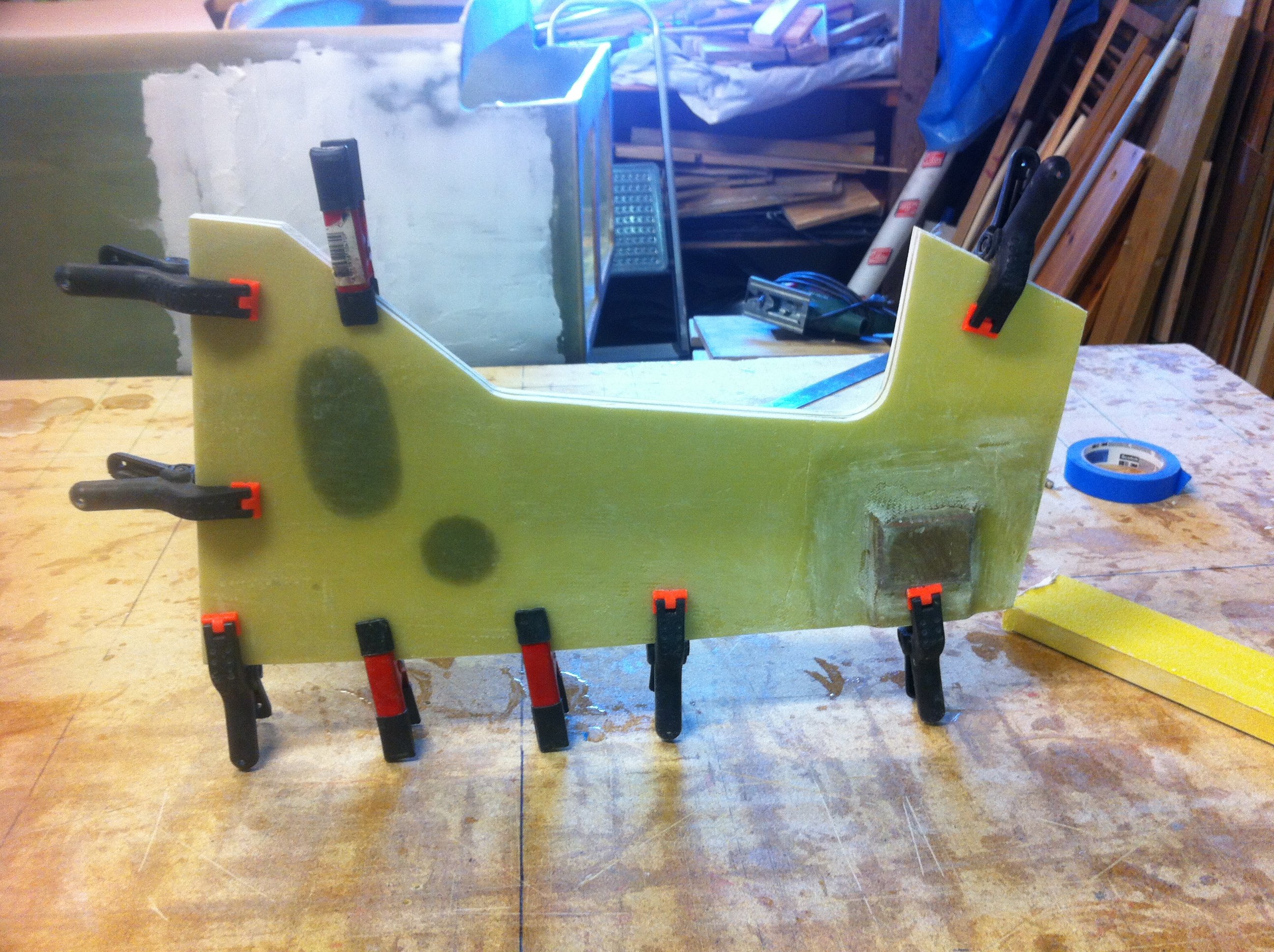
2013-04-7: After cure I sanded the edges and mounted the two parts together and made sure that all edges was aligned and equal.
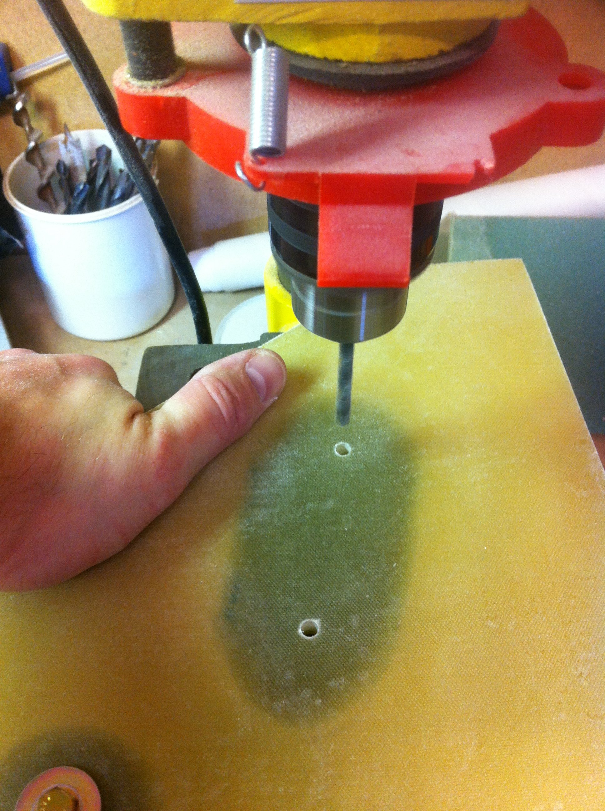
2013-04-7: Using the drill-press to make accurate holes for the actuator and the MKNG6, as well as the holes for the rudder-pedals. Since the plans describes the holes for the manual nose-lift, I had to do some research to find out the differences when using Wilhelmson’s nose-lift. It says it is a bolt-in replacement, so after searching the mail-archives I found that Jack W. says we should drill the holes as stated in the plans. There are two differences, the lowermost hole is omitted (I have not made any hardpoints there as one sees in the pictures), and the plans says to omit one of the upper holes on one side, that is not so when I use the electric lift. I have also planned for this by adding hardpoints on both sides. Other than that there are no differences.
2013-04-7: I started by drilling up the hole for MKNG6, and bolted the two NG-30’s together by an AN4-bolt trough the pivot hole for MKNG6. Then I drilled the lower hole for the actuator on one NG-30 with a #12-drill-bit (actually I used a 5mm), mounted the NG-30’s together again and drilled through the other using the newly drilled hole as a pilot. Then I put an AN3-bolt through these holes and bolted the NG-30’s together again before I drilled the last holes, including the holes for the rudder-pedals. Used the drill-press all the time to ensure the holes are absolutely perpendicular to the NG-30.
2013-04-7: I removed the glass on the inside of NG-30 where the MKNG6 pivot assembly is coming. Removed the peel-ply which was added in the early phase of NG-30, chamfered the edges and sanded the exposed glass with 36 grit, and finally glassed with 2 BID as per plans, overlapping the edges with 1″. Peel-plied the whole thing and set aside to cure in the heat-tent.
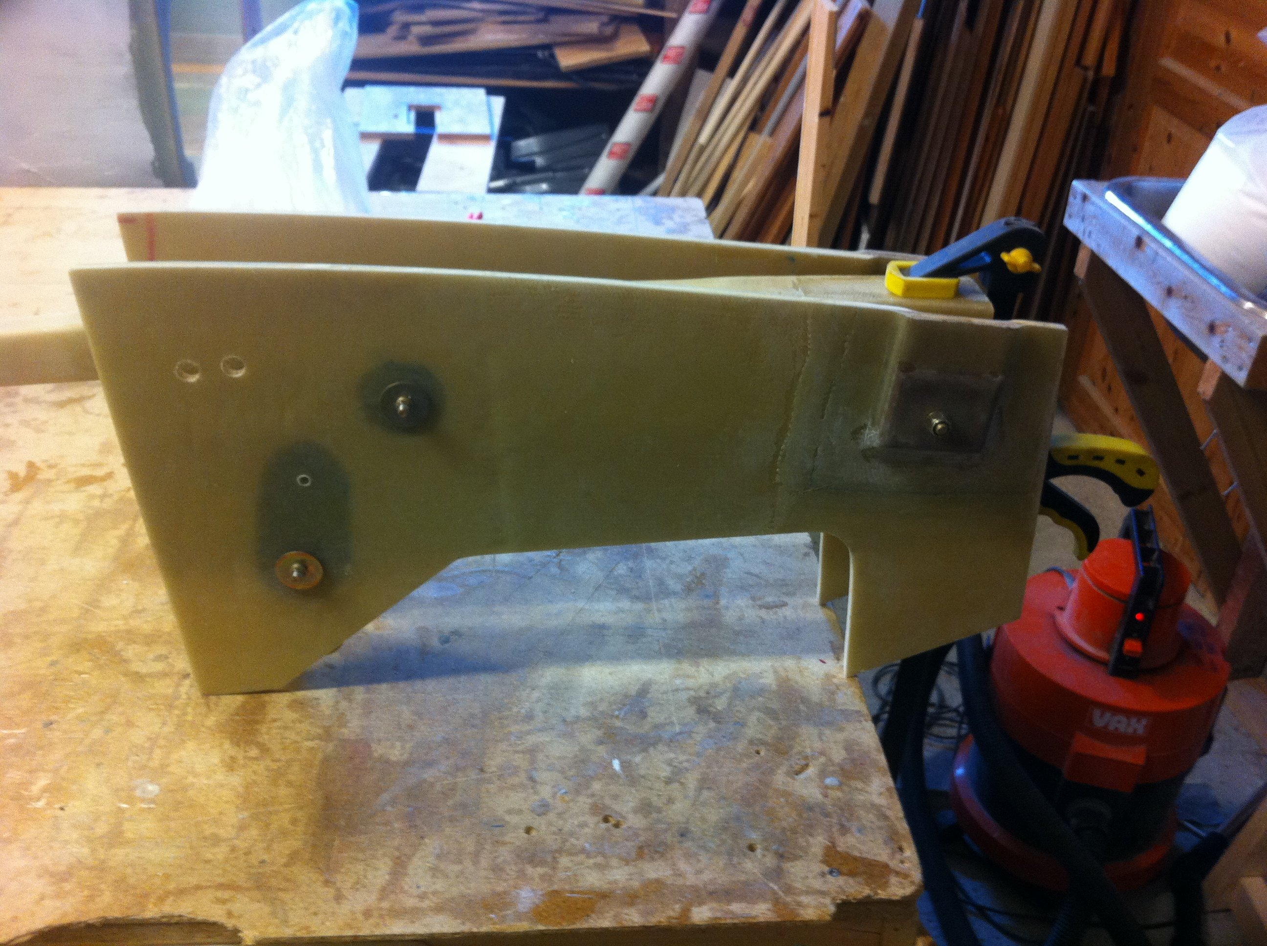
2013-04-12: Drilled all the mounting holes up to their final size and mounted NG30 temporarily.
Started: 2013-04-01
Ended: 2013-04-12