
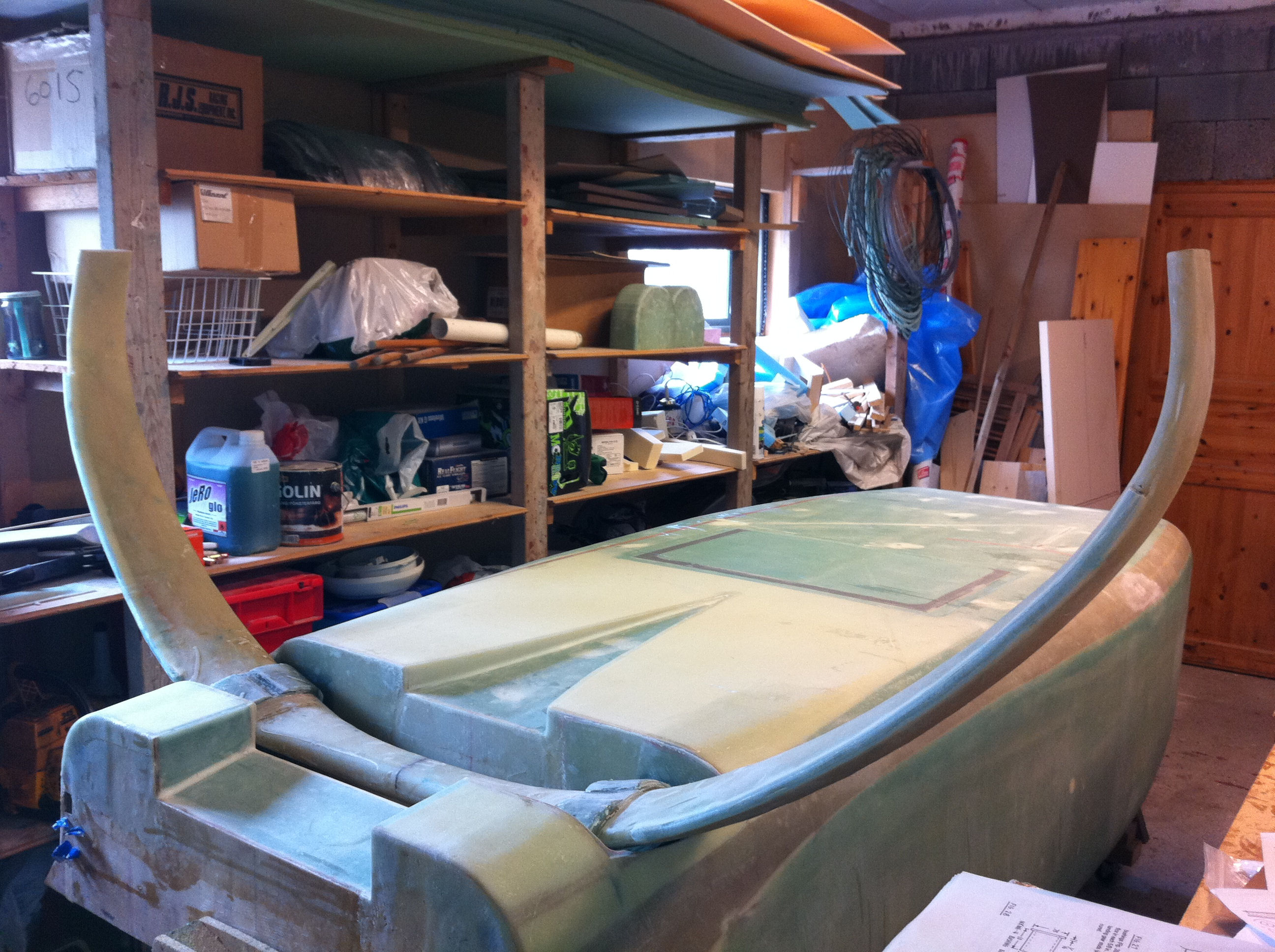
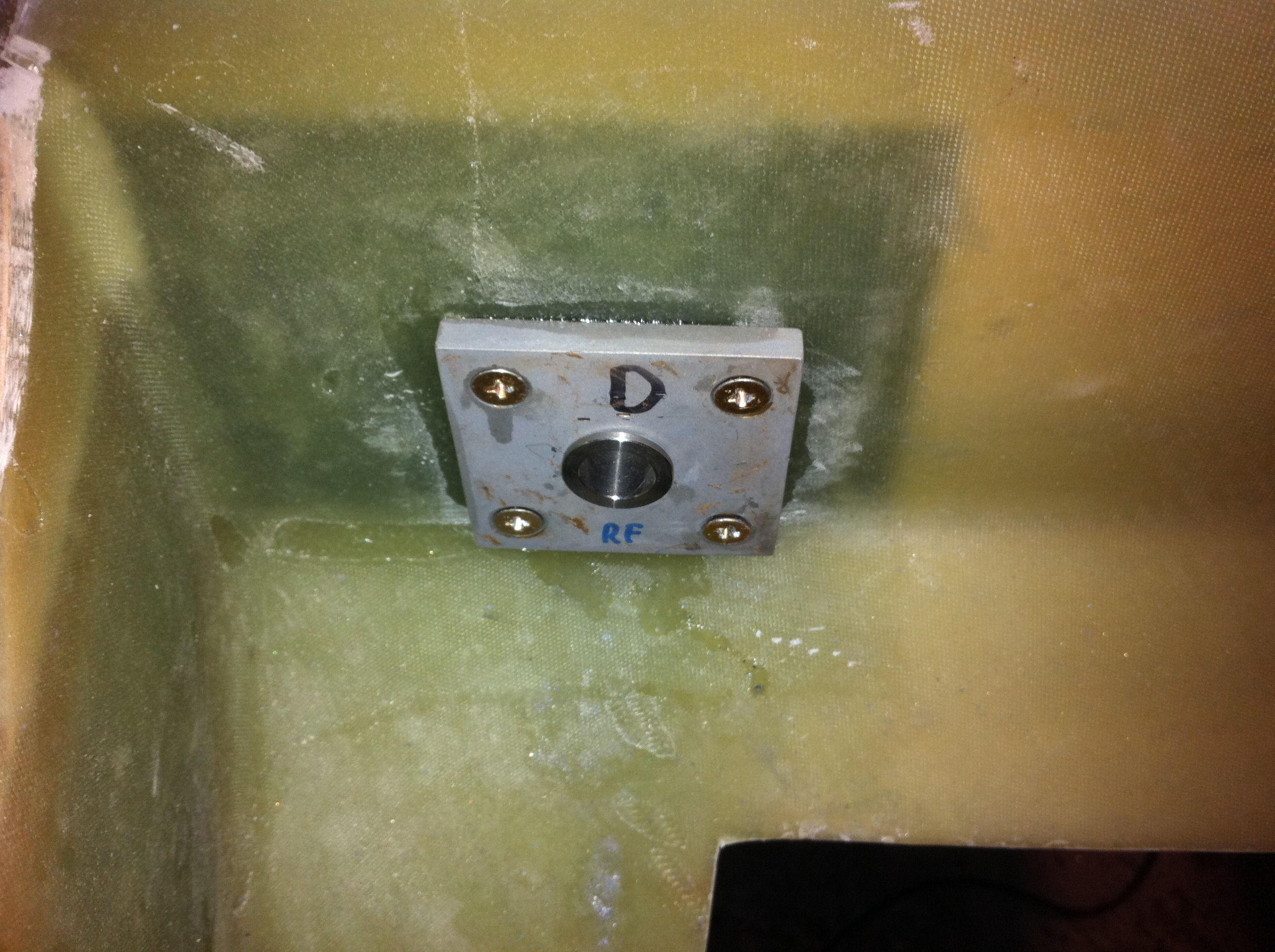
In this step I will make four attach-tabs. This is the connection-points between the landing-gear and the fuselage.
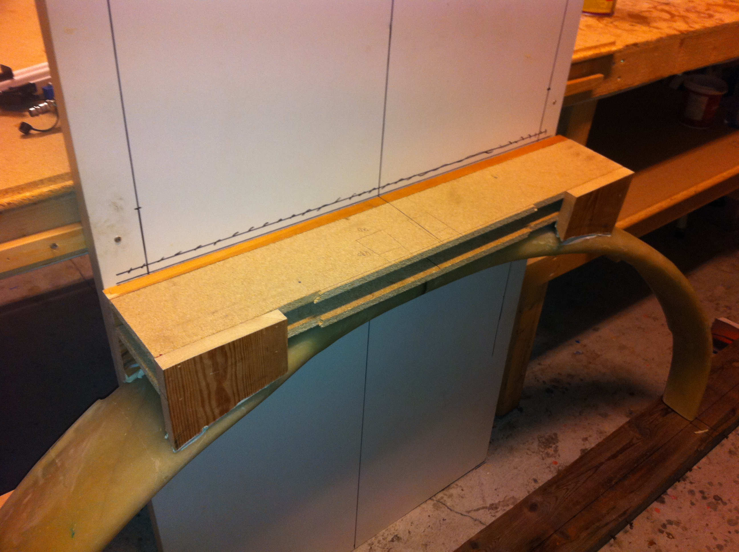
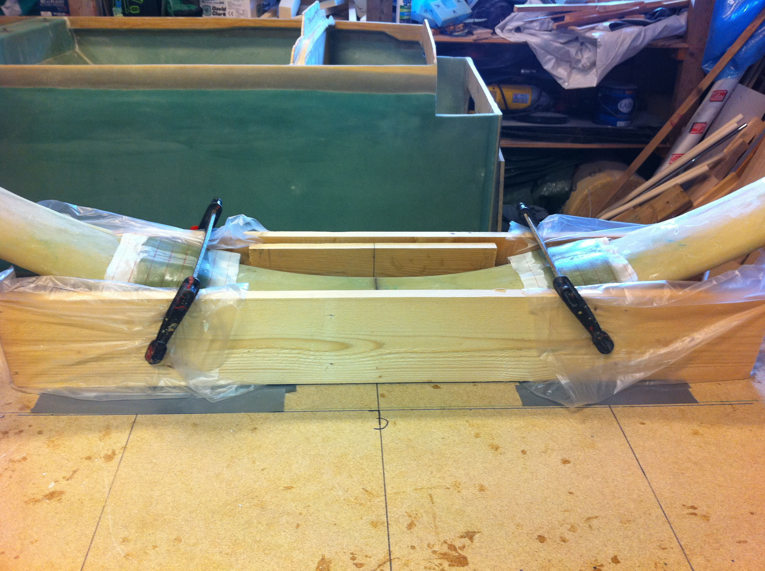
2011-03-27: The first thing to do is to place the strut on a level surface, leaning towards a horisontally back-plate. By measuring 9.25″ from the leading edge of the strut to the back-plate I have the strut placed at the correct angle for the box I must make ontop. This wooden-box is just to be used as a formwork to make the attach-tabs. The geometry has to be accurate, since this defines how the landing-gear will be mounted in the airplane later on.
2011-04-02: The strut is now placed upside-down on the box ontop of the table. I have made markings on the table according to plans, leveled the table and the top of the strut. Then I have measured the vertical line from leading edge of the strut down to a line 9.25″ from the aft face of the strut. I had to shim the box to achieve this. Finally I bondoed the box to the table and made to extra stiffeneres on each side, bondoed to the strut and screwed and bondoed to the table.
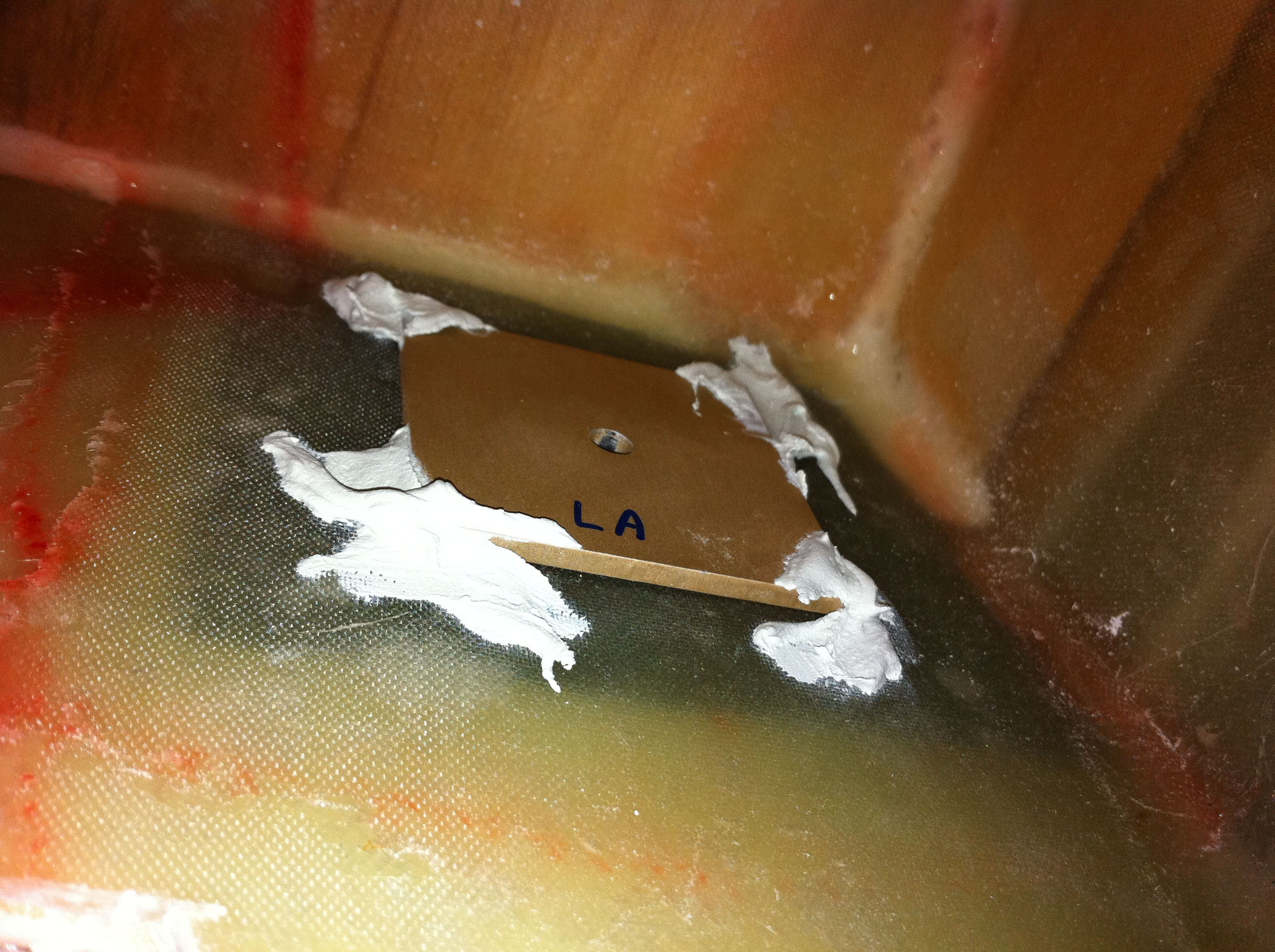
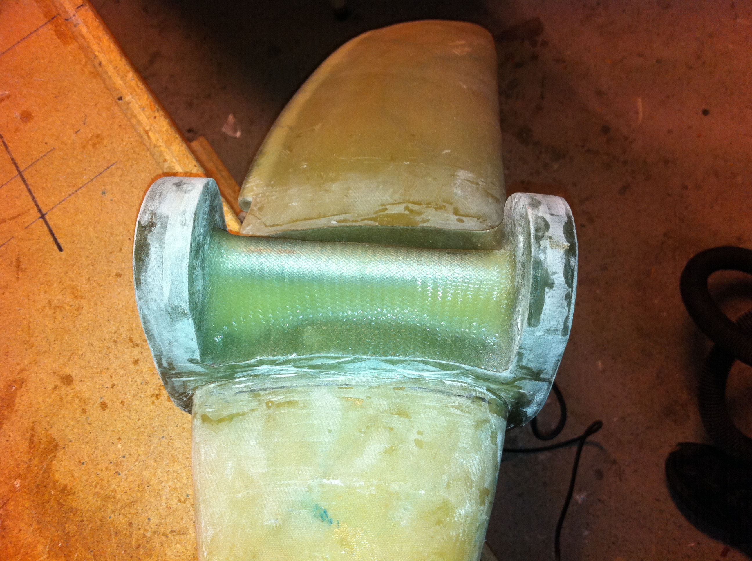
2011-04-02: The tabs are marked on the wood as well as the positions for the holes. The next step is to glue a tremendous number of plies here to make the tabs…
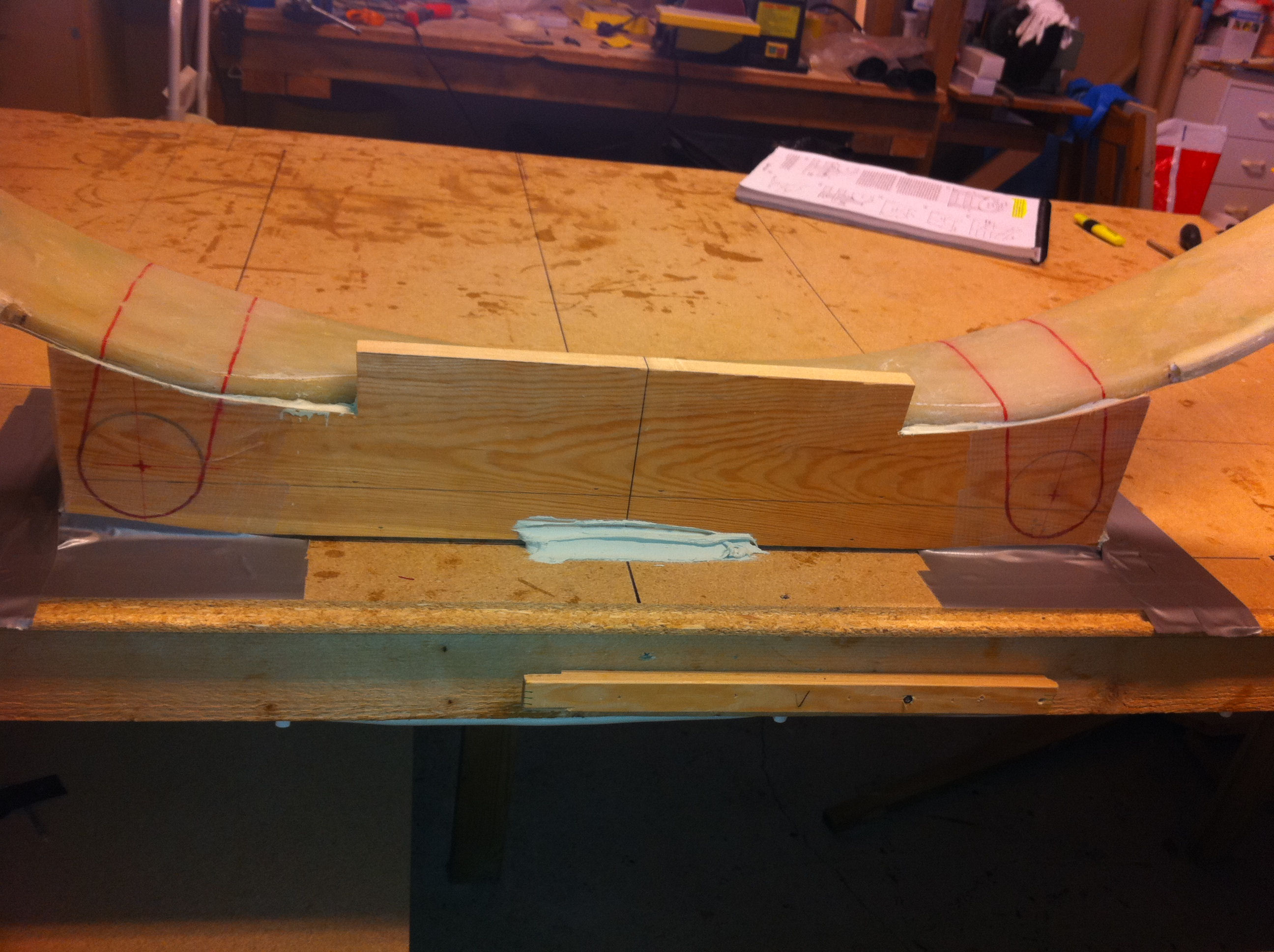
Note: This picture shows that I am goofing up something here. The position of the mounting-holes are way too low. I made the same measuring mistake that several other builders have made. Unfortunately I forgot to read all the builder-logs this time before I started. Luckily I discovered the error before I started to trim the tabs. So – what’s the fault here? I made the marking for the holes on a line .75″ above the highest point of the struts centerline. This is WRONG. The correct measurement should be .75″ from the highest point of the strut at the 13″ line drawn on both sides of the strut. After reading the plans once again I see that this is exactly what the plans tries to tell us, but it’s easy to misunderstand this point, as several has discovered. I will send a note to Marc Z. to get this in the FAQ (even he made this mistake!).
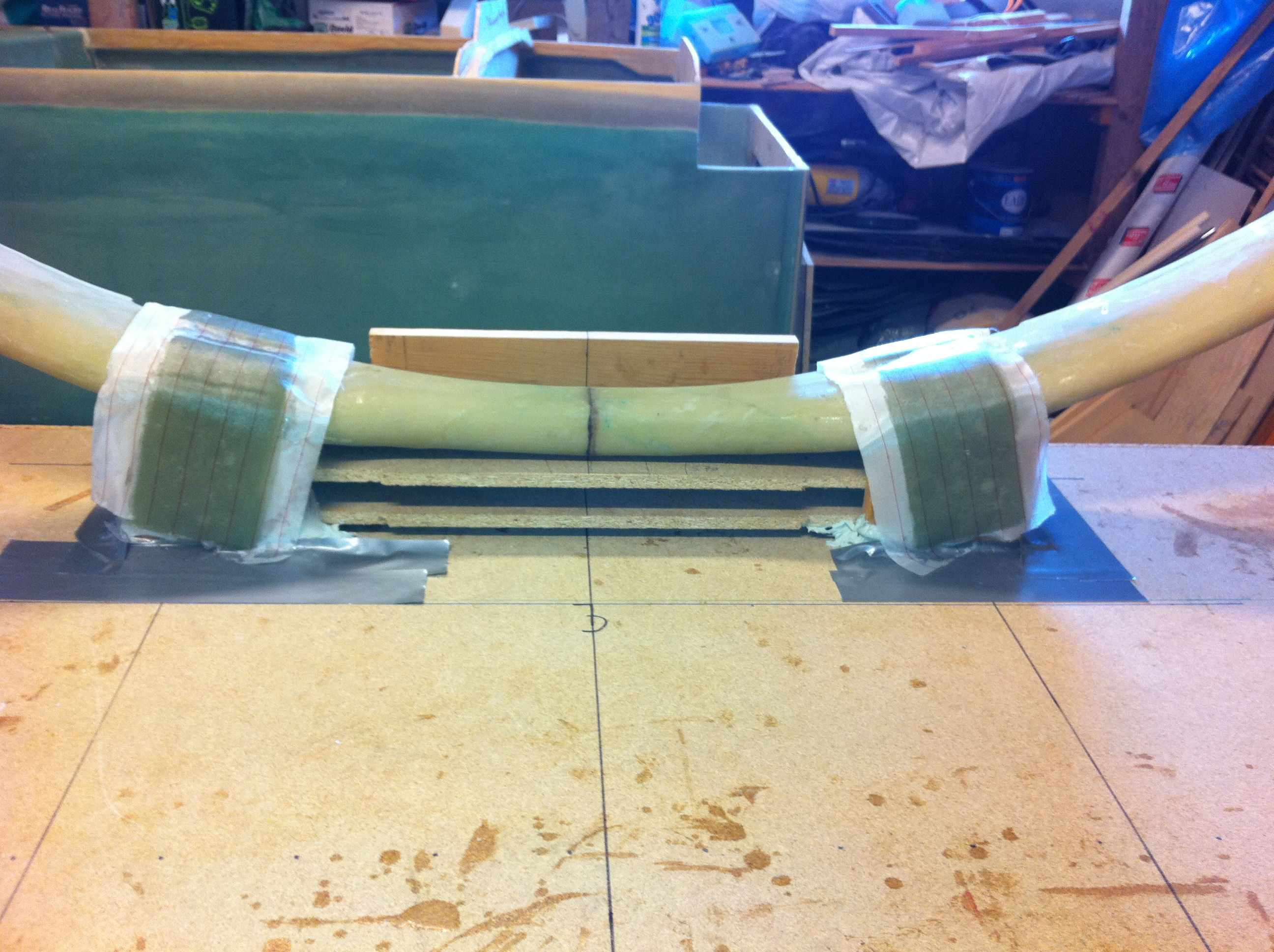
2011-04-10: The first part of the tabs are finished and peel-plied. It consists of 25 plies of UNI followed by 20 plies of BID.
2011-04-10: When let to cure the still wet tabs are compressed between a couple of wooden-blocks to squeeze out excess epoxy and to make the layup as compact as possible – without over-tightening!
2011-04-16: The first part of the tabs are trimmed and the holes are drilled. The tabs are prepared for the next layers. The holes are filled with candle-wax.
2011-04-20: The corners are filled with flox to make a radius before glassing the inside of the tabs.
2011-04-20: The inside tab-layups are finished and peel-plied. Some wooden blocks are placed to compress the tabs a bit.
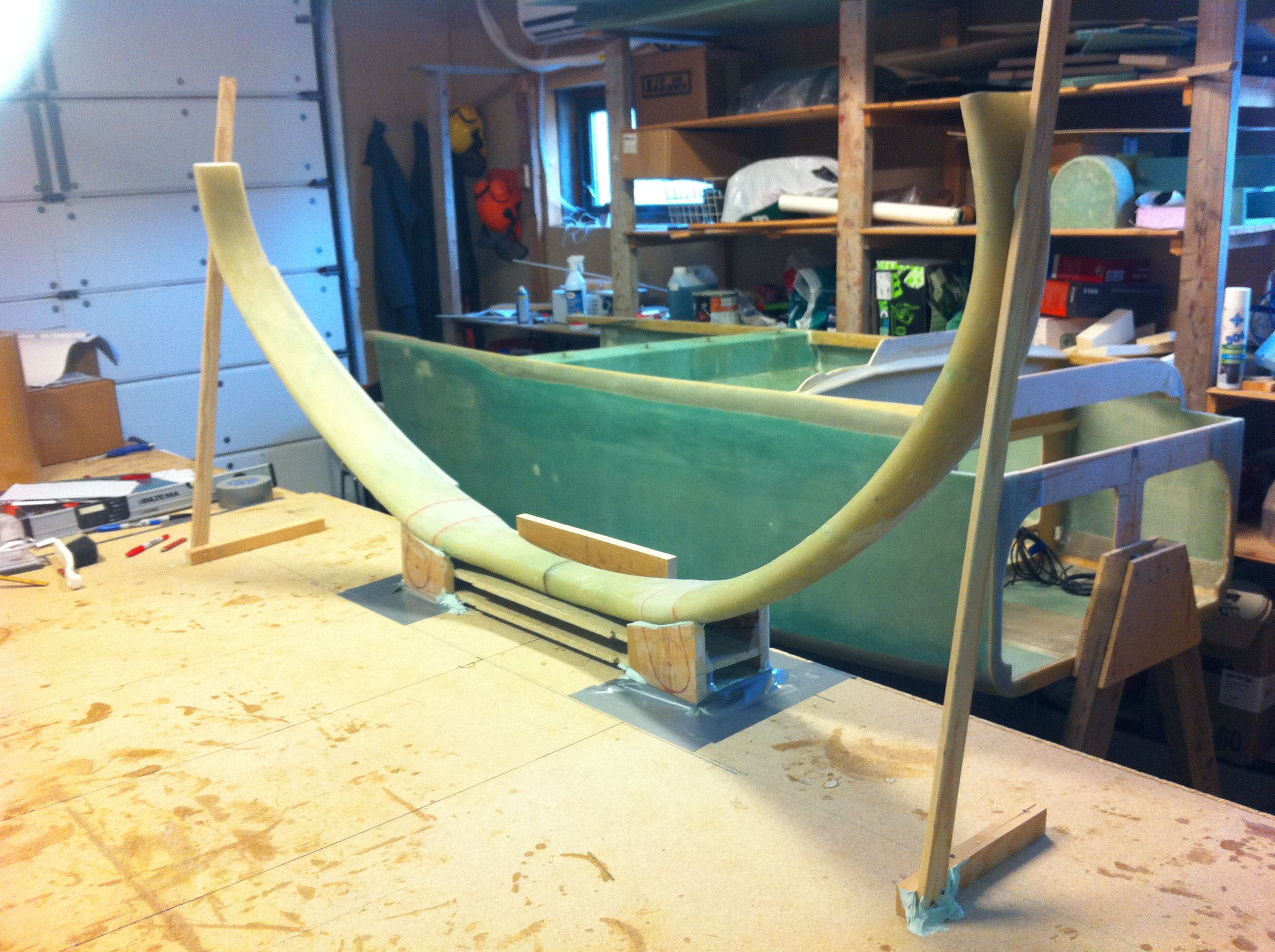
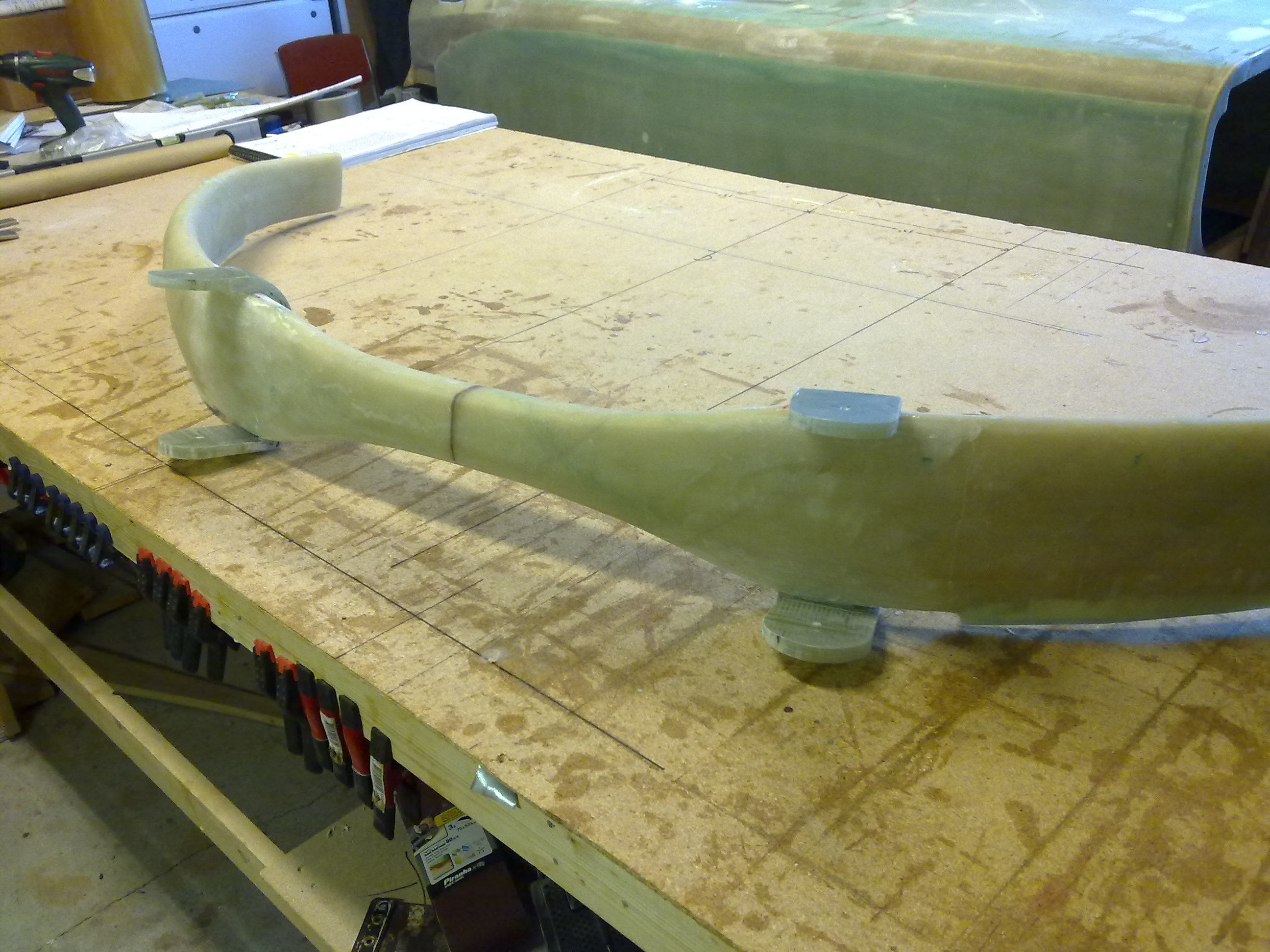
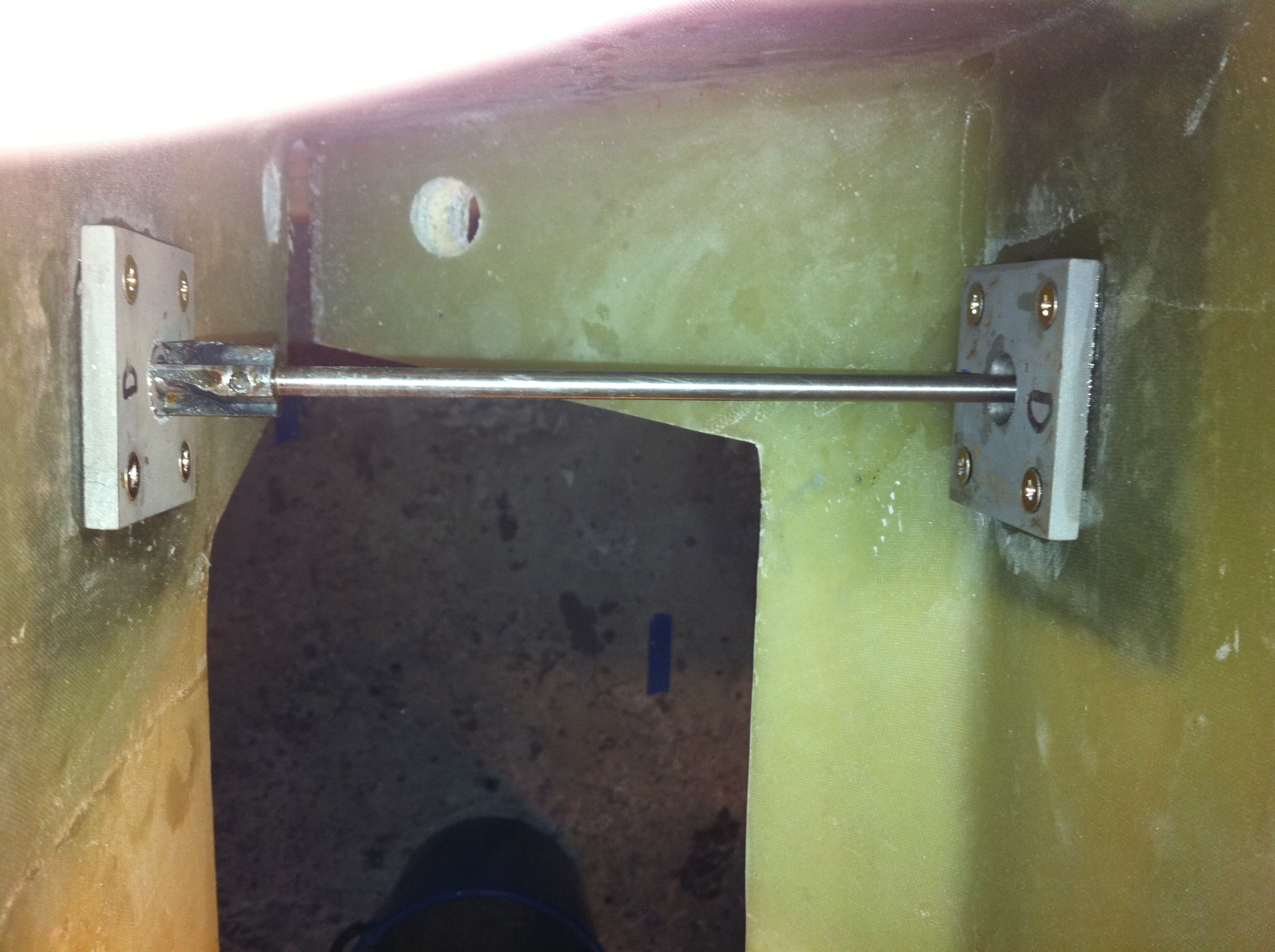
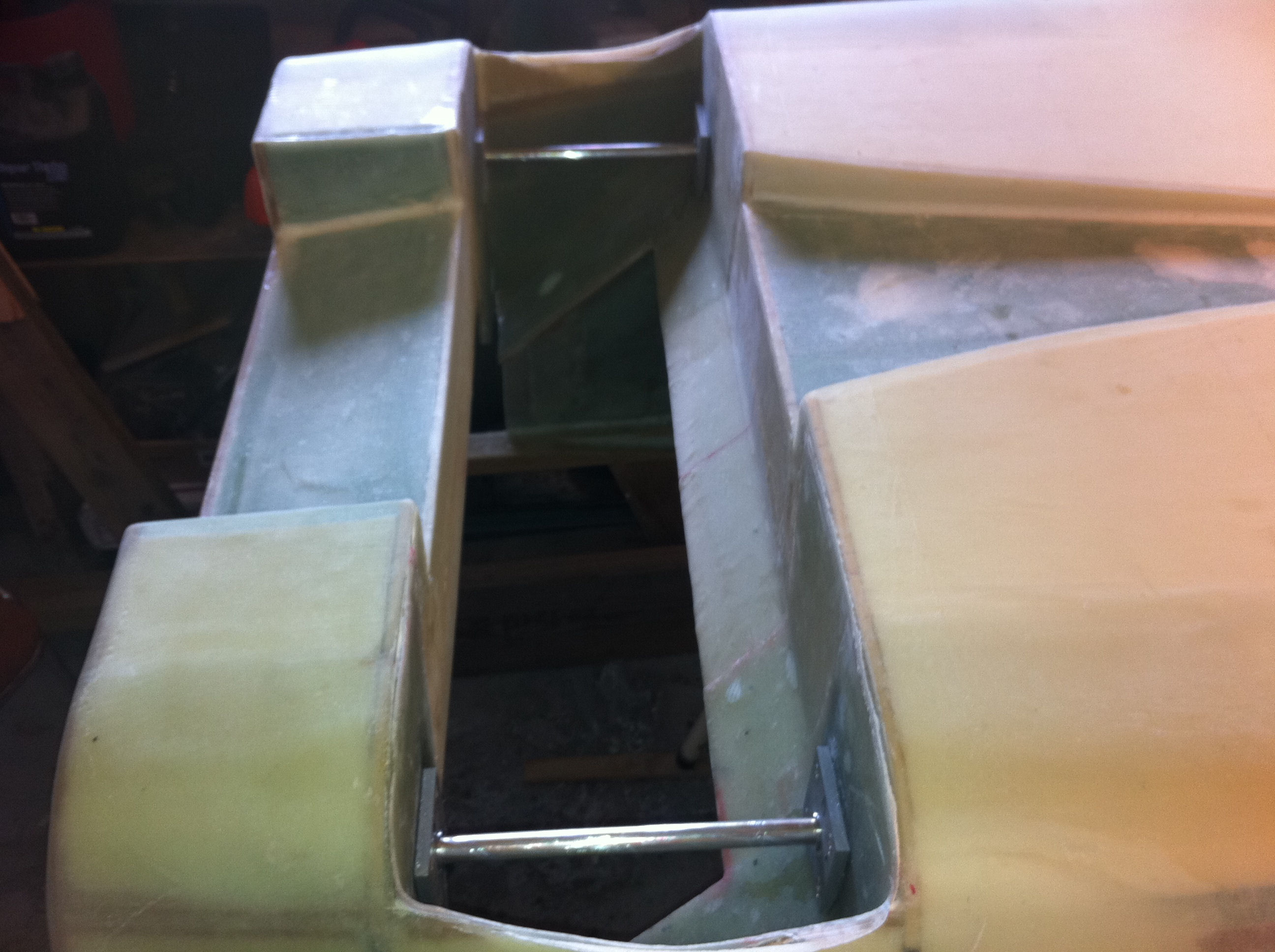
2011-04-25: The tabs are finished and the MLG (Main Landing Gear) are test-fitted into the tub. The holes were almost perfect, the right hole in the aft bulkhead was 1 mm out of line. I just trimmed this hole and placed two 1/4″ rods into the holes to position the MLG temporarily. The next step is to level the fuselage and measure the position of the MLG compared to the tub. The result after leveling off the fuselage gave me that the leading edge of the main gear was only 4mm in front of the correct position. This is easy to compensate when I am mounting the axels.
2011-05-08: I bought the MK1 and MK2 from the Cozy Girrls among some other stuff. I followed the plans all the way, not much to say here. I used bondo to fasten the MK1…
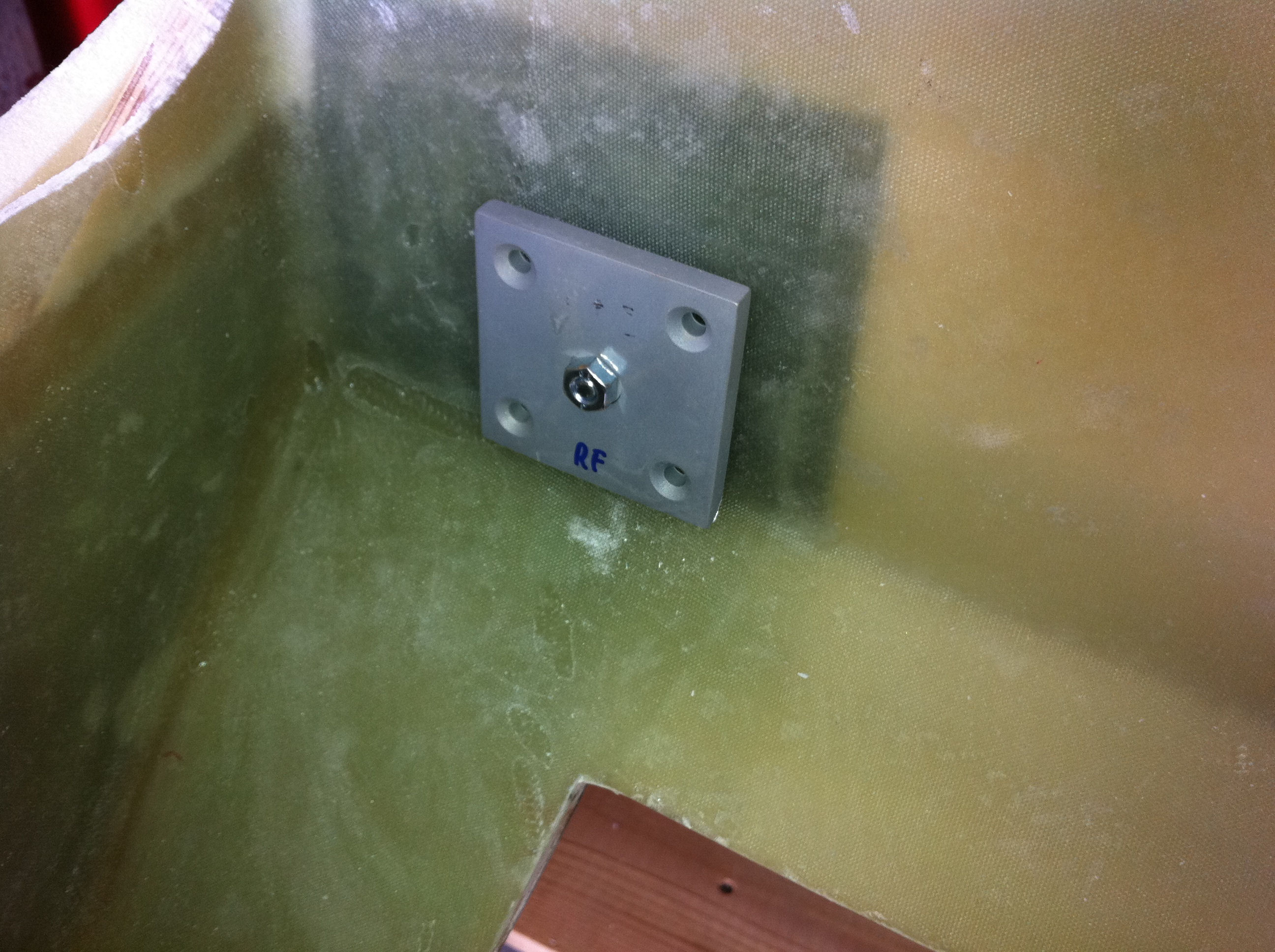
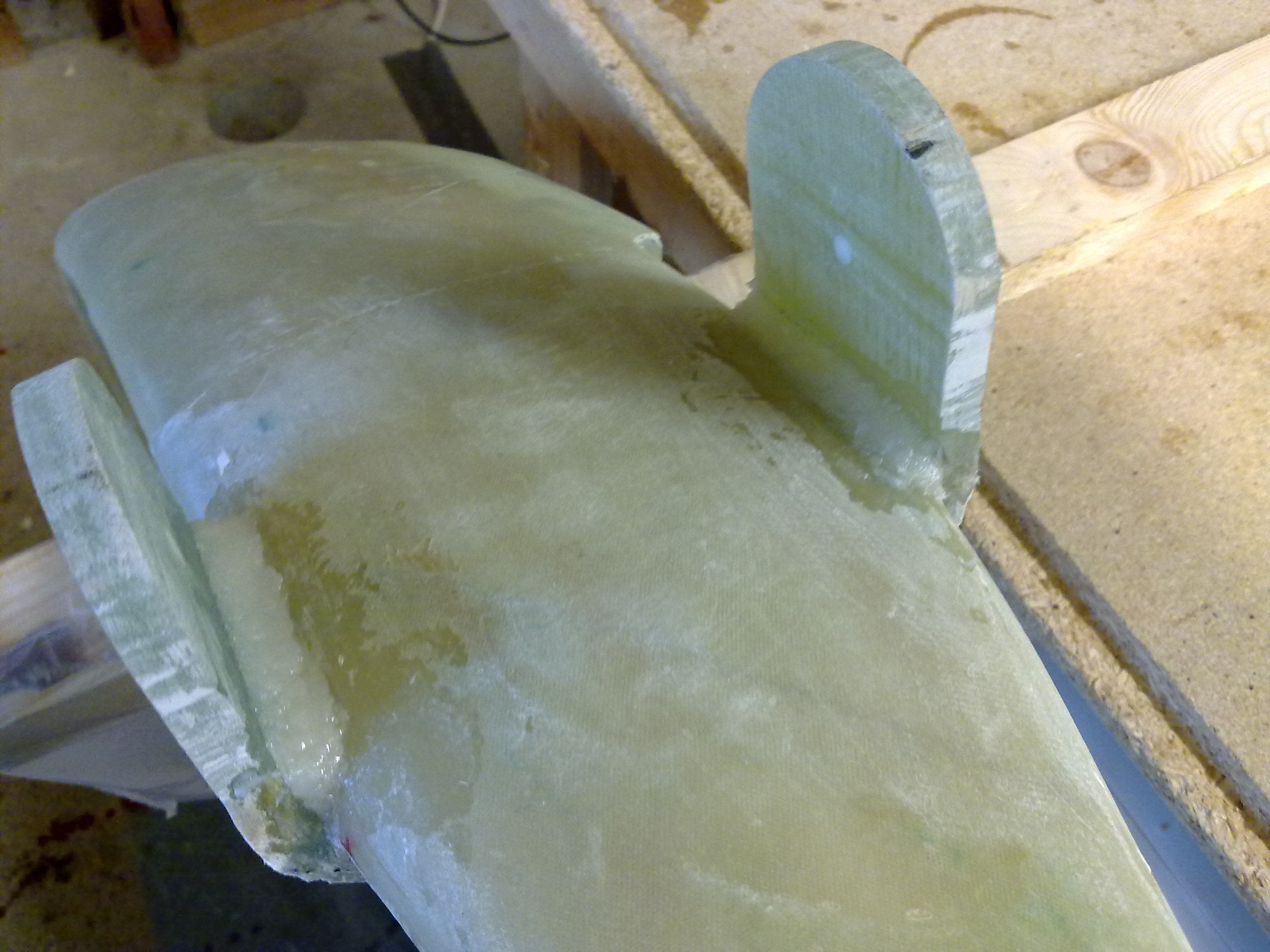
2011-05-08: Then I mounted the MK2 on the other side of the bulkhead with a temporary bolt. One thing here with the front MK2 – I needed to shape the part that rests against the sloped part of the bulkhead – actually round the backside of the MK2 a bit. This is due to the flox-corner I made here initially. I have read in the archives that other builders have encountered the same.
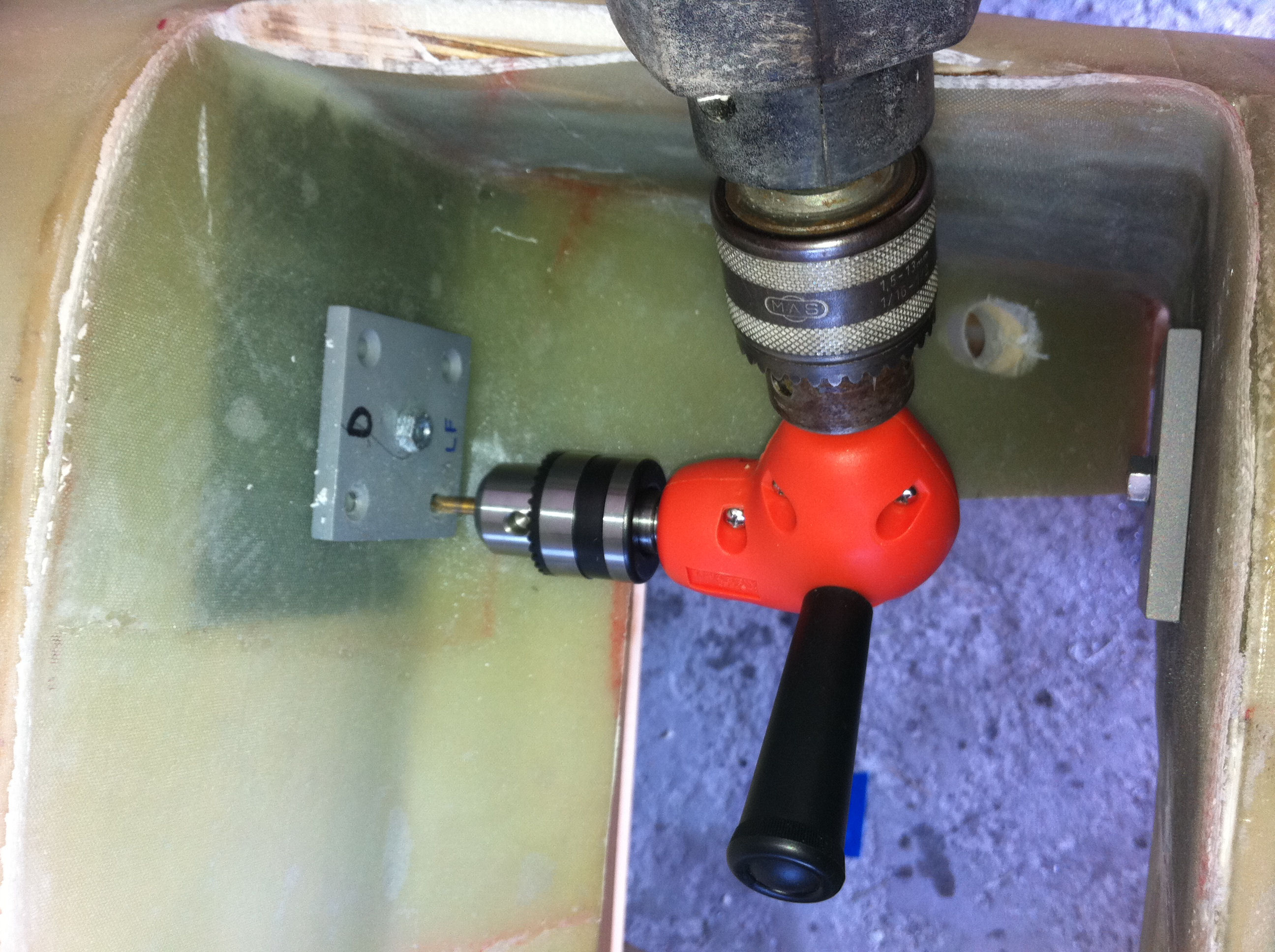
2011-05-08: I needed to drill four holes in every MK1 using the pre-drilled holes already present in the MK2 as a template. To manage this I had to run to the hardware-store to buy still another tool – the angled drill-adapter.
2011-05-13: Time to open up the holes with the special-tool from ACS. It is a hard job as the tool gets very hot. The trick is to drill for 20 seconds a time, chill down the drill-bit in water, drill 20 secs on the other hole, cool down and so on until you are through. It took apporx 1 hour to come through two holes, i.e. the left and right front holes, then an other hour to make the two other holes. I also needed to use an extender on the shaft as it was just too short to drill the last part of the aftmost MK1…
2011-05-14: The MG-4-bushings are floxed in place. I had one issue here as the aft and front holes on the right side was not parallell to each other. After inserting the bushings, I inserted the studs and on the left side the two holes matched perfectly, on the right side however I had to elongate the front hole a bit to make the stud hit the aft hole. This was filled with flox.
An other thing was that the stud didn’t slide through the bushings at all. Looked like the bushings was too tight. When I tried to slide the studs through the MKMGA’s they went through, but at the same time some of the coating on the studs was planed off. After a couple of times in and out of the MKMGA’s the studs slid easy through the MKMGA and by magic it also slid through the MG-4-bushings!
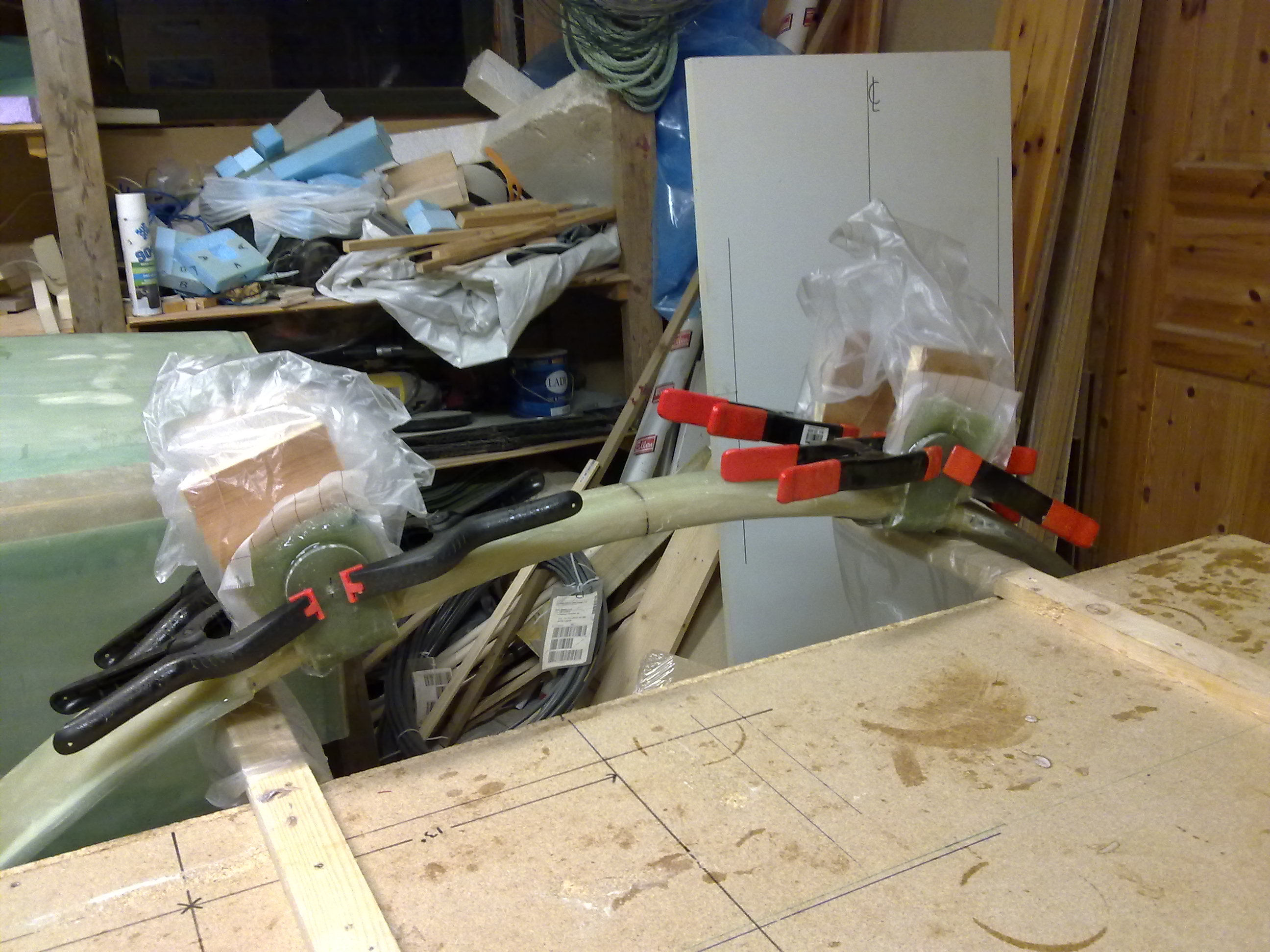
2011-05-14: Here the MG-4-bushings are floxed in place and the studs are inserted to fix the MG-4 while they are curing.
2011-05-16: Final step is to make a foam-filling under MKMGA, and cover with 2 BID. I chose to make a flox-bed instead of the foam to make things even more secure. I have read several other builder-logs where they have done the same thing. Probably not neccessary, and a bit heavier (just a fraction!), but I don’t think that this matters right here.